I do not understand this. Do you talk about circuit in post 6
http://www.diyaudio.com/forums/solid-state/160285-class-crossover-distortion-1975-a.html#post2067705 ?
T2 must be npn, T8 must be pnp. The driver stage Vas has a "current source" output.
Interesting that positive supply is grounded.
http://www.diyaudio.com/forums/solid-state/160285-class-crossover-distortion-1975-a.html#post2067705 ?
T2 must be npn, T8 must be pnp. The driver stage Vas has a "current source" output.
Interesting that positive supply is grounded.
about the original post 197I do not understand this. Do you talk about circuit in post 6
Your post 201 does not fit the schematic of 197.
No "Vas" (Voltage Amplifier Stage ?) This is a follower output without voltage gain.
"It must be a voltage source" .. please, I need common phrases to understand what you mean.
WHAT must be a voltage source? Is the circuit in WW a voltage source or not? WHY must it be a VS?
Please share your knowledge if possible.
If I edit your suggestions of post 198: "That amp (which amp ?) was always operated with a speaker (what kind of "speaker"?) and the nasty surprise came when hooked to a commercial 3 way speaker (when I hooked up a different speaker - not the first one ?) with a complicated passive crossover....wild oscillations broke out at the or near the crossover frequencies. Thus end of story". (which story ? In contrast to that we read in your first post "I had such an about 50 watts amp done it works until today ( I use it for burn-in of loudspeakers by a 24 h driving at 16 hz ) . The circuit does not require adjustment of idling current or dc offset. It has excellent stability of parameters versus operating temperature".
By the way "wild oscillations broke out at the or near the crossover frequencies" means you made a sweep ? Did you think about why it happened? Does this observation make the topology useless or is is probably only a consequence of your particular execution? Can you confirm this does not happen with other power amps ?
In order to avoid more confusion:
Do we agree to talk about the letter in WW April 1975 By N. Visch as seen in my post 197 (sorry it was not shown before) ?
Did you set up an amp like this at the time with a driver stage similar to the diagram in your post 6 (which does not work if done as shown there) ?
Have you been satisfied by the properties of it for decades as described in your post 1 ?
Now you tell us "end of the story" about the same or probably something different ?
Your jubilee post 200: "made a quick sim according to schematic post 197...see for yourself".
I do not see the result of a sim.
You started a thread because you missed an original source. The idea was probably you found the schematic useful.
I delivered the original paper. Please explain why it is not useful any more remembering the old saying "Verstärker schwingen immer, Oszillatoren schwingen nie".
Thank you.
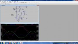
Well the schematic post 6 is not at all wrong it is single supply. It worked well as subwoofer amp - but shouldn't. Possibly it oscillated as well but that were not audible with a woofer. An EF i badly missing. The Visch topology has voltage gain 1 so for a 30 volt rms output there has to be a voltage gain of at least 30 somewhere in front end. That is provided in post 6. But a simple sim displays the problem. Specify a SPICE sine source with serial 1 k and see the Visch breaks out in half wave oscillations. So the driving source must be a voltage source having very low impedance, say 10 Ohms. That can be achieved somehow but if one wants a not switching amp just take Elvee's Circlophone. Ok the Circlophone has standby power dissipation of 12 to 15 watts that is a disadvantage while the Visch gets along with 1 watt or less standby. After all in a standard listening room an amp puts out less than 1 watt 90% of the time according to amplitude statistics. I could run a sim with the schematic post 6 adding a Darlington EF in front of the Visch input to provide low driving impedance but i somehow think that is not a brilliant idea.
At least in sim the Visch does not operate as Visch described. For negative input the VCE of Q3 drops to about 200 mV and thus Q3 does not conduct ( blue Iq) and consequently the output voltage is limited . This is valid if dc input is 0 Volts. That makes the amp rather sensitive to bias voltage at input.
Attachments
I use this class B for 10 years with great pleasure.
if you want more information, do not hesitate

Thanks but i have tons of fat BJTs...no Mosfets.
The idea of Visch was about the same as that of the Quad dumping amp : no adjustment of bias no thermal compensation. I did some sims testing various predrivers with the amp being loaded with a sim of a vented bass box - subwoofer. It could be used as a subwoofer driver. But with a simmed load 3 way passive speaker it just didn't work. ( With the original BJTs) . It could be that it is voltage feedback and the original (!) 2N3055 are rather slow devices they become even slower when current-driven. I didn't sim with contemporary BJTs with much higher fT.
- Status
- This old topic is closed. If you want to reopen this topic, contact a moderator using the "Report Post" button.
- Home
- Amplifiers
- Solid State
- Class B w/o crossover distortion (1975)