Now the circuit works also by me correctly (still by simulation - at least concerning the DC conditions).Here are the voltages:
Only my first estimate in my previous post causes the simulation error. My second estimate (cathode of D2 seems to be also wrong connected) wasn't right.
Attachments
Last edited:
Time to wake this thread up again.
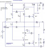
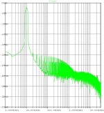
Here's another modification to the Visch topology - a buffer that combines the reactive bridge from the Quad current-dumping circuit with a simplified Visch darlington output stage, driven by an ultra-low distortion opamp. It's biased in Class-AB with about 25 mA quiescent current in the output stage. There's still a lot of optimization to be done, but the initial results look very promising. At 10V output amplitude into 8 ohms, THD20 is below -120 dB, with H2 dominating.
It's probably most suitable for driving low-impedance headphones, but it could also be used as a line-level buffer. All the devices (except the opamp) are commodity jelly-beans types - the output darlingtons could probably be substituted by TIP122s with nominal impact on sonics.
Attachments
Last edited:
It's missing the junctions where the wires meet at 90 degrees - an LTSpice .wmf problem. Just assume that all wire-crossings have a junction, except where there is a U-shaped dog-leg at the crossing.
The load is driven by U2, U3 (darlingtons) through L1 (part of the reactive bridge C1-R3-L1-R4). There's a small feed-forward correction (a few mA) from the opamp through R4. It's possible to decrease distortion a bit by decreasing R4 (and rebalancing the bridge), but at some point the odd-harmonic character of the LME49860 output stage will start dominating.
The load is driven by U2, U3 (darlingtons) through L1 (part of the reactive bridge C1-R3-L1-R4). There's a small feed-forward correction (a few mA) from the opamp through R4. It's possible to decrease distortion a bit by decreasing R4 (and rebalancing the bridge), but at some point the odd-harmonic character of the LME49860 output stage will start dominating.
It's missing the junctions where the wires meet at 90 degrees - an LTSpice .wmf problem. Just assume that all wire-crossings have a junction, except where there is a U-shaped dog-leg at the crossing.
The load is driven by U2, U3 (darlingtons) through L1 (part of the reactive bridge C1-R3-L1-R4). There's a small feed-forward correction (a few mA) from the opamp through R4. It's possible to decrease distortion a bit by decreasing R4 (and rebalancing the bridge), but at some point the odd-harmonic character of the LME49860 output stage will start dominating.
Thank you for your explanations.
It does, and it doesn't:Elvee, I don't mean to nitpick but your VischB crosses above 1A.
It is one of the difficulties with this circuit, the dynamic stability of the quiescent current.
The first pic shows the circuit operating at a very low power.
The Iq is a nice ~30mA. Note however that the positive and negative crossings occur at a different level. This is caused by the time-constant of the Visch "memory cap". Yet, the frequency is not very low.
The second picture is made at 25V^ output; now the crossing occurs at 1.8A.
This could be seen as a "feature": dynamic biasing following the music level.
But in addition to the increased dissipation, it also has a major drawback: it takes time to settle to the new condition: the third pic is taken under the same conditions, but at the beginning, when the circuit didn't yet have time to adapt.
There is a severe clipping for a number of ms.
When the circuit is near idle condition, it spends most of the time servoing the Iq.
But at higher current levels, the waveform on D1 becomes trapezoidal, and the servo action occurs only in the linear mode, during the transitions.
But if, on the other hand the circuit is not perfectly balanced, the duty cycle of the trapeze (almost a square wave) will dominate the average voltage and cause a shift in the bias.
I have made a number of real prototypes, and the problem seems almost impossible to solve satisfactorily.
Attachments
one that works (for 19 years)
D701/703 are real geraniums. In simulation I used scottky's. The sound is to die for (nikko alpha 220/230). ( Below )is the OPS , the VAS/input stage is the typical symasym/balanced topology , I have used a current sourced blameless instead with 10ma current. I still works ...
OS
D701/703 are real geraniums. In simulation I used scottky's. The sound is to die for (nikko alpha 220/230). ( Below )is the OPS , the VAS/input stage is the typical symasym/balanced topology , I have used a current sourced blameless instead with 10ma current. I still works ...
OS
Attachments
Now, thats more like B... 100mA crossing for the big transistors.
Late discovery: With Schottkys as shown, R1 R2 can be Muntz'd.
There is some improvement, now the Iq varies from ~25mA for no signal to ~1A at 25V^.
But that's not ideal yet.
And I fear the behavior at 20Hz will be worse.
perhaps the servo methody from follow link can converted to the Vish topology:
http://www.diyaudio.com/forums/solid-state/40877-n-channel-mosfet-amplifier-servo-bias.html
http://www.diyaudio.com/forums/solid-state/40877-n-channel-mosfet-amplifier-servo-bias.html
Hi Hahfran.
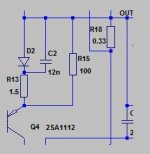
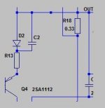
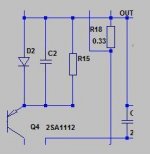
In your post 159 ".... R13, R15, C2 (D2?) are for fine tuning the harmonics spectrum. A truly wonderful descending spectrum was achieved."
There are other configurations of C,R, D. Phase Linear type and Arcam A60 type.
My questions:
You tried these other types? Or you proposal is the best configuration?
Thanks
GEirin
Attachments
I found this thread when searching for something else.
It seems nobody posted a link to the original article in Wireless Word, April 1975.
This issue can be seen here:
http://www.americanradiohistory.com/Archive-Wireless-World/70s/Wireless-World-1975-04.pdf
American Radio History: Documents from the History of Radio TV and FM
broadcasting and Electronics has an impressive compilation of
different magazines.
The article "A NOVEL CLASS B OUTPUT ?" which is in fact a letter to the editor
written by Nico M. Visch, Rotterdam, is on page 166 (p. 52 of the pdf). I copied it
at the time and still have it in my folder. This was the first time that I saw the expression
"a long-tailed pair without a tail".
The page is attached to this post. I think the last sentence of third paragraph should be
"So, with this type of output there is an optimal value for the quiescent current" - not
"optional" as in print.
It is not clear how the thread starter arrived at his driving stage with voltage gain. Is
it from a second article ?
Attachments
I eventually got the original wireless world but it may sit on some backup i cannot find now. That amp was always operated with a speaker and the nasty surprise came when hooked to a commercial 3 way speaker with a complicated passive crossover....wild oscillations broke out at the or near the crossover frequencies. Thus end of story.
If this amp is claimed to be "sensitive to reactive loads" it should be investigated.
We do not know where the driver stage that you used came from and the actual
setup, wiring etc. may be a factor also.
The original contribution (you don't need to find it on paper, because it is in post 197)
has the current amp stage only. The schematic in your post 6 can not be working as
shown.
We do not know where the driver stage that you used came from and the actual
setup, wiring etc. may be a factor also.
The original contribution (you don't need to find it on paper, because it is in post 197)
has the current amp stage only. The schematic in your post 6 can not be working as
shown.
- Status
- This old topic is closed. If you want to reopen this topic, contact a moderator using the "Report Post" button.
- Home
- Amplifiers
- Solid State
- Class B w/o crossover distortion (1975)