I'm hoping someone has some experience with these amps and can give some good advice or point me in the right direction.
I have a Carver TFM-4.0, which is the same as the M4.0t and very similar to the TFM-42 and TFM45. The left channel is about 5-10dbs stronger then the right. I checked the amp boards and the components are within a couple of ohms of each other. Neither channel is offset more than 15mv.
Any help would be greatly appreciated!
Try and get in touch with Anatech on this forum, he's resident Carver guru. If I recall correctly there is an adjustment on each board that controls the amount of feedback (gain) and is really touchy. The last one I worked on I ended up replacing the control with a multiturn trimmer and it was much easier to adjust. This might explain the difference in gain between the two channels. See what Anatech says before doing anything, these are not your normal amplifiers.
Craig
Craig
Thanks for the advice. I have the service manual for this amp and I've worked on a M1.5t before, but I am by no means an expert in Carver products. It looks like the 2 trimmer pots on the amp boards are for the bias and damping. There is also another pot on the power supply to control the high rail voltage.
Anatech, could you provide any guidance?
Anatech, could you provide any guidance?
Does anyone else have any thoughts on this??? Anyone???
I studied the schematic, and there is an op amp (to invert the signal for bridging) only on the left channel, not the right, which I find a very odd design. It seems strange to me that carver didn't use an identical design for each channel and put active circuitry in one channel but not the other. Basically, for the right channel, the signal goes straight through to the amp board, but for the left it goes through an op amp first. In my case the left channel has more gain than the right. I swapped out the op amp with a new one to see what would happen, but the problem remains.
The other thing I noticed it that there is a FET that is supposed to mute the signal (part of the protection) on each amp board at the beginning of the signal path. I did check using a transistor/FET checker and it seems good.
Any other thoughts? The service manual mentions in the repair checklist to verify that there is the same gain in each channel. Is there some way to balance or adjust the channels?
Hi Steve,
Nice amplifier. Your problem is a known fault with the damping control oxidizing. As Craig correctly pointed out, it is a terribly sensitive adjustment.
The official fix involves the use of a resistor in series with a control that is half the resistance of the original, the balance is made up in the added resistor. Okay, easier to adjust, but still suffers the same failure mode. So does your fix Craig, sorry.
My solution solves this as an issue for all time. The negative points of doing things my way is that the absolute gain is not as consistent from amplifier to amplifier (but it's darn close!). The other negative point is that there is no longer any gain adjustment available, which means you have to balance the channel gains by padding the resistor (increasing the gain as I recall). Since you only ever do this once, it's not too great a drawback in my opinion. That's why I do it, how many times should I charge a person per amp to fix the same problems? Once in my book.
What you need to do this is a very accurate ohmmeter, a very stable sine wave generator at 1 KHz and a very accurate AC voltmeter. A calibrated scale in dB really helps here, and one that measures level differences from a random level is even better. These requirements are the same no matter which way you decide to service this issue. The equipment I have used are HP / Agilent pieces, a 34401A DVM (I can't say enough positive things about this meter!) and a 339A distortion measuring set, I did use a Leader LAG-120B previousely, so any service grade oscillator will work as long as the distortion is well below 0.5% - perferably lower (the LAG-120B was confirmed at 0.05%, 339A down at 0.0018%). I'm not sure how a signal with higher harmonics will behave, and the Carver recommended equipment was a Sound Technology as I recall. Okay, some of this may be out of reach, so do your best. It is possible to rent test equipment for a week, and that may be the way to go.
Order some 1K00 1% metal film resistors. Get 10 as you are going to match a pair close to the target value of 1K. I am assuming that you have a selection of carbon film or metal film resistors as well. You will probably need some in the 82K ~ 820K range to pad the matched pair with. Hey, I told you this was a sensitive adjustment! Remove the two damping controls, may as well measure them. Remove any resistor that was in series as well. (measure the series resistance of both installed if there is a series resistor added). You should have a figure that is really close to 1K, unless the control is really bad or someone has fiddled with these already. Guess what? Your matched pair of 1K00 resistors will replace the pot (and pad resistor if it exists). Leave about 1/4" of lead from your new resistors out the foil side. You will tack the padding resistors across one of these pair.
Now the fun stuff begins. Make sure you don't have any solder splashed where you'll regret it, same for wire clippings. Turn the amplifier on, any motor boating should be gone now. Set your audio generator for an output of 0dBm or so, any convenient level for you and 1 KHz sine. Higher levels will not change anything, a load will but it will change both channels roughly the same. Set a reference level on the channel with the lower output and determine what the difference is between channels. Turn the power off on the amp and allow the supplies to discharge. I use an 8R0, 250 watt dummy load for this, it's available on my bench and easy to get to. Take a resistor, say 620K, and tack that across the resistor in the lower channel. Don't trim the leads yet. Recheck for solder splash or wire clippings again, then turn the amp back on. Retake the channel levels and determine how much change there was in the channel you "played" with. The level should have gone up some. If it went the wrong way, sorry - I got confused, so turn off and place the resistor on the other channel. Otherwise, the two channels should now be closer in level. Too low - use a lower value resistor to pad, too high, increase the value of the padding resistor.
I normally went for a channel difference of 0.05 dB or better (fewer dB difference). That's because I was doing "Canadian Factory service" and had to make sure there could be no complaints about quality. In the real world, most amplifiers are not this close in level, and speakers can be 2 dB out or more. Then, there are the room acoustics on top of all that. So, get it close but don't go for perfection. Remember that all the component parts inside the amp also have a temperature co-efficient and most signal sources are not going to be that close either. Everything is going to shift with time and the seasons.
Now, if you can not see the channel differences when you take your first reading, the equipment you are using is not good enough. Rent something for a week (Agilent, if you're smart) and so some other service work as well. Do try out a 34401A or similar meters (they have more now in that family - and mine is still current even after more than 15 years! ). If you do any kind of electronics work at all, you will find a 34401A more than up to the task. In fact, you'll find this meter makes your life a lot easier.
No, I don't work for Agilent or any test equipment sales or service company.
Let me know how this works out for you Steve. Craig, I'm afraid that you really should do your amp again before it starts motor boating again.
-Chris
Nice amplifier. Your problem is a known fault with the damping control oxidizing. As Craig correctly pointed out, it is a terribly sensitive adjustment.
The official fix involves the use of a resistor in series with a control that is half the resistance of the original, the balance is made up in the added resistor. Okay, easier to adjust, but still suffers the same failure mode. So does your fix Craig, sorry.
My solution solves this as an issue for all time. The negative points of doing things my way is that the absolute gain is not as consistent from amplifier to amplifier (but it's darn close!). The other negative point is that there is no longer any gain adjustment available, which means you have to balance the channel gains by padding the resistor (increasing the gain as I recall). Since you only ever do this once, it's not too great a drawback in my opinion. That's why I do it, how many times should I charge a person per amp to fix the same problems? Once in my book.
What you need to do this is a very accurate ohmmeter, a very stable sine wave generator at 1 KHz and a very accurate AC voltmeter. A calibrated scale in dB really helps here, and one that measures level differences from a random level is even better. These requirements are the same no matter which way you decide to service this issue. The equipment I have used are HP / Agilent pieces, a 34401A DVM (I can't say enough positive things about this meter!) and a 339A distortion measuring set, I did use a Leader LAG-120B previousely, so any service grade oscillator will work as long as the distortion is well below 0.5% - perferably lower (the LAG-120B was confirmed at 0.05%, 339A down at 0.0018%). I'm not sure how a signal with higher harmonics will behave, and the Carver recommended equipment was a Sound Technology as I recall. Okay, some of this may be out of reach, so do your best. It is possible to rent test equipment for a week, and that may be the way to go.
Order some 1K00 1% metal film resistors. Get 10 as you are going to match a pair close to the target value of 1K. I am assuming that you have a selection of carbon film or metal film resistors as well. You will probably need some in the 82K ~ 820K range to pad the matched pair with. Hey, I told you this was a sensitive adjustment! Remove the two damping controls, may as well measure them. Remove any resistor that was in series as well. (measure the series resistance of both installed if there is a series resistor added). You should have a figure that is really close to 1K, unless the control is really bad or someone has fiddled with these already. Guess what? Your matched pair of 1K00 resistors will replace the pot (and pad resistor if it exists). Leave about 1/4" of lead from your new resistors out the foil side. You will tack the padding resistors across one of these pair.
Now the fun stuff begins. Make sure you don't have any solder splashed where you'll regret it, same for wire clippings. Turn the amplifier on, any motor boating should be gone now. Set your audio generator for an output of 0dBm or so, any convenient level for you and 1 KHz sine. Higher levels will not change anything, a load will but it will change both channels roughly the same. Set a reference level on the channel with the lower output and determine what the difference is between channels. Turn the power off on the amp and allow the supplies to discharge. I use an 8R0, 250 watt dummy load for this, it's available on my bench and easy to get to. Take a resistor, say 620K, and tack that across the resistor in the lower channel. Don't trim the leads yet. Recheck for solder splash or wire clippings again, then turn the amp back on. Retake the channel levels and determine how much change there was in the channel you "played" with. The level should have gone up some. If it went the wrong way, sorry - I got confused, so turn off and place the resistor on the other channel. Otherwise, the two channels should now be closer in level. Too low - use a lower value resistor to pad, too high, increase the value of the padding resistor.
I normally went for a channel difference of 0.05 dB or better (fewer dB difference). That's because I was doing "Canadian Factory service" and had to make sure there could be no complaints about quality. In the real world, most amplifiers are not this close in level, and speakers can be 2 dB out or more. Then, there are the room acoustics on top of all that. So, get it close but don't go for perfection. Remember that all the component parts inside the amp also have a temperature co-efficient and most signal sources are not going to be that close either. Everything is going to shift with time and the seasons.
Now, if you can not see the channel differences when you take your first reading, the equipment you are using is not good enough. Rent something for a week (Agilent, if you're smart) and so some other service work as well. Do try out a 34401A or similar meters (they have more now in that family - and mine is still current even after more than 15 years!
). If you do any kind of electronics work at all, you will find a 34401A more than up to the task. In fact, you'll find this meter makes your life a lot easier.No, I don't work for Agilent or any test equipment sales or service company.
Let me know how this works out for you Steve. Craig, I'm afraid that you really should do your amp again before it starts motor boating again.
-Chris
Hi Craig,
Well, what you did was very similar to the official fix from Carver land. That fix addressed the sensitivity of the adjustment, yet it didn't treat the root cause. So what you did years ago was about the same thing most technicians were doing. The units were also well out of warranty by that time anyhow, you should see what many "3rd party" service shops did to these poor amps.
The complaint was normally not noticed until the amplifier began to motor-boat. On a Carver M4.0, this is a very scary (sometimes destructive) event. Just imagine the output swinging from +125 VDC to -125 VDC at low frequency! When I looked at the official service action from Carver after observing one in the fault condition, it became obvious that the "fix" was all about buying time. I guess the hope was that these amps would be thrown out or sold before the fault reoccurred.
So, I assume you sold your amp and got another. What did you buy instead?
-Chris
Chris,
It was a repair for a friend long ago, don't know if it ever happened again. Of all the trimmers in thousands of amp all over the world why does THAT particular trimmer oxidize? I don't remember any motor boating, I do remember a full volume midrange squeal that fried the unobtainium midrange driver on my Westlake speaker though. Of the thousands of units I've repaired I've only run across two Carver amps, the other one was broken solder joints on one of the PCBs.
Craig
I just wanted to thank both you guys for helping with this. The diagnosis was right on. And you are not kidding that the pot is touchy...blink and it is off a couple hundred ohms. I think it would be impossible to acheive the level of precision that Anatech referred to with that pot. Also, the comment about the motorboating concerned me a little. I'm going to try Anatech's suggestion with the permanent fix. Thanks again!
I would have done the same if I had known it was a common problem. I had the current service manual but there was no mention of this problem. Chris had a definite advantage being a service center and seeing the problem many times. I've only repaired two Carvers and that was many years ago. The internet has made things much easier too! The real fix is not that hard to do, it all depends how much time you want to spend. Good luck!
Craig
Craig
Hi Steve,
The level of accuracy I mentioned is easily matched and even exceeded. I do think there is little point in going further. In fact, I did mention that I used that as a limit for performance in order to eliminate the normal criticism that crops up from armchair critics. Even at this level of matching, I did have the odd person mention that wasn't close enough! Shows you what they know I guess.
So again, that level of matching is easily attainable as long as you are using an HP or Agilent DVM in the 344xxA series or equivalent. If I had the money, I'd buy the newer 34410A or 34411A to go with my older 34401A. I am more than sure you can rent one as well. Those sound card audio programs might even get you that close, but you need an input attenuator and protection for your sound card if you are going to attempt that route.
Hi Craig,
That trimmer applies positive feedback to affect the level of damping. It's a questionable adjustment if you ask me, but one that would be necessary to help mimic the sound of another amplifier (like a tube amp). In it's position, manufacturing (accountants) felt they could eliminate the normal padding resistors - making this % adjustment far too wide. This ends up being an extremely touchy adjustment as a result. Yamaha was famous for this type of situation, so much so that we called it "Yamaha Syndrome" at the shop. I'm sure that other brands share that oversight. Anyway, the official Carver modification partially corrected the situation by including one of the two normal padding resistors that restrict the range of adjustment with the trimmer control. However, oxidized contacts would have exactly the same effect on the operation of the amplifier.
The normal failure progression begins with level changes with perhaps some noise. As it becomes more severe, the level changes become more pronounced until the amplifier finally becomes unstable. At that point, the oscillation is normally low frequency - full amplitude (nasty!). Of course, depending on exact average impedances, I guess you could have a higher frequency tone result, still at full amplitude. No driver lasts very long when an amplifier of this power becomes unstable and behaves badly!
Being the National service center for Canada helped more than being simply a warranty shop. We had access to the engineering personnel, which was very helpful. We could make an observation in the field, figure out the best we could what the failure mechanism might be, then report to an engineer directly. The information you have in the manual was the "fix" that I only applied a couple times. I just figured that they had not got to the root cause of the issue. Most modifications probably were worked out in Carver's service department before submission to the engineering department. If the fix looked good, an engineer would sign off on it. Of course the engineering department did figure out most of the ECO's themselves, but took other suggestions under advisement. The person I talked to most was Vic Richardson, the same name you can see approving engineering change orders that you followed. That man was very good to talk with, and very sharp as well. The service department there? Well, let's just say they seemed to be convinced that everything is a secret and no one else could do their job. It was just easier to avoid speaking with them. They were supposed to be my contact, but it just didn't work at all.
-Chris
I wish I had found this thread a few months ago.
Tha tthud thud thud thud I used to get form the TFM 42 is called motorboating huh ??? OK well live and learn.
My RP2 pot -well, caused a lot of motorboating ... and I guess some scorch and some light burn marks on the pins connecting to the power amp boards. Of course crappy cold soldering gave way ,and stopped the sparking, and motorboating etc etc ...
I resoldered it and set the pot to where it works ... but is very very low on power. Sounds like a 10 watt amp.
Here is the setting on the RP2 pot. Any help is appreciated. Can I try to turn the pot a bit counterclockwise and hope that it wont go up in smoke. I am hoping to see that it can make somewhere more than 10 watts.
Thanks.
Srinath.
Attachments
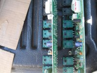
If I set that pot to less than 6 oclock position, I run the risk of motorboating. 5 o clock it motorboated like crazy.
Should I put a 1k resistor and the adjustable 500 ohm pot. I am pretty sure I cant do the mod anatech did. I dont have that sort of equipment.
Thanks.
Srinath.
Should I put a 1k resistor and the adjustable 500 ohm pot. I am pretty sure I cant do the mod anatech did. I dont have that sort of equipment.
Thanks.
Srinath.
- Status
- This old topic is closed. If you want to reopen this topic, contact a moderator using the "Report Post" button.
- Home
- Amplifiers
- Solid State
- Carver M4.0t with weak channel