I have a Yamaha RX-530 stereo receiver that has an open power transformer on the primary (the big one). I am hoping that someone might be able to measure the secondary AC voltage going to the power amplifier so that I can find a suitable replacement.
I do have a transformer that is a bit bigger and has a secondary voltage of 26-0-26VAC and another winding with something like 16VAC (for tuner, preamp and lamp). Is this too high of a voltage?
I do have a transformer that is a bit bigger and has a secondary voltage of 26-0-26VAC and another winding with something like 16VAC (for tuner, preamp and lamp). Is this too high of a voltage?
thermal fuse
check the transformer for a thermal fuse in line with the mains on the transformer. Usually a 2nd tap right next to one of the mains. Ck if open.
It may take some digging, but bypass and check for power up
Replace fuse if bad. ( I usually permantly bypass, but not as safe)
Gotta pic of the transformer taps?
What is the max voltage rating on the power supply caps?
What is the amp chip ID#?
26vac will get you around 40vdc. That would be good for most chipamps.
Last edited:
No obviouse fuse thermal fuse...
There is really not much to the transformer, if there is a fuse it is bearried deep within the windings, impossible to get to without pulling the laminations apart.
The amplifier has 2SC3855/2SA1491 much nicer than a chip output, the power supply caps are 6800uF 56V, I suspect this receiver puts out between 50-60 watts 8 ohms.
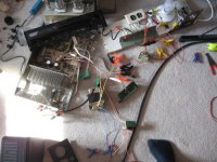
I may post some pics of the receiver and transformer, all I really need to know is what the voltages are on the original transformer so I can be sure the thing won't blow up, but I will be sure to use my series light bulb.
There is really not much to the transformer, if there is a fuse it is bearried deep within the windings, impossible to get to without pulling the laminations apart.
The amplifier has 2SC3855/2SA1491 much nicer than a chip output, the power supply caps are 6800uF 56V, I suspect this receiver puts out between 50-60 watts 8 ohms.
I may post some pics of the receiver and transformer, all I really need to know is what the voltages are on the original transformer so I can be sure the thing won't blow up, but I will be sure to use my series light bulb.
caps are the limit, else boom
I'd think you'd be ok.
You are likely low on voltage with the other transformer. It likely ran higher V but not > 56v, the transistors you noted are 10a 200v.
How many output transistors per channel?
single pair ~40v for 60 watts
dual would be greater
I'd think you'd be ok.
You are likely low on voltage with the other transformer. It likely ran higher V but not > 56v, the transistors you noted are 10a 200v.
How many output transistors per channel?
single pair ~40v for 60 watts
dual would be greater
Last edited:
That is allot more voltage than I expected! 48V cuts pretty close to the max rating of the capacitors. When I look at how big the original transformer is, it really seems undersized for what the amplifier requires. The one I have is a bit bigger even though it has lower voltages, so it will most likely perform better even if there is less output.
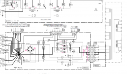
Thanks for the info sajti, it is very helpful to know as I can now test the amplifier, the power supply schematic will be useful as well, I might change some values. I will also take some pictures and post them at some point.
Thanks for the info sajti, it is very helpful to know as I can now test the amplifier, the power supply schematic will be useful as well, I might change some values. I will also take some pictures and post them at some point.
I actually got the receiver to work of the 26V-0-26V transformer and I found a 12V-0-12V for the preamp and tuner section. The entire thing worked without any problems.
I would however like to have the schematic for the Tone control/Final stage of the receiver as I would like to experiment with using a tube in place of the op-amp in the final stage. I have pleanty of spare windings on the power transformers and lots of space to wire a 12AU7 tube to the circuit board when I remove the op-amp.
Thanks for the help guys.
If you want to "repair" your old transformer it is probably not as bad of a job as you think. The thermal fuses are not real practical to wind in so they place them right under the lead pads. However, you will normally have to desolder the copper shield if you want to re-use it, and there is of course some minor surgery involved to resect the fuse. It would then be entirely your responsibility to make sure the transformer doesn't help introduce you to some local firemen.
- Status
- This old topic is closed. If you want to reopen this topic, contact a moderator using the "Report Post" button.
- Home
- Amplifiers
- Solid State
- Open Transformer in Yamaha RX-530 receiver