Welcome! This thread is for all those who bought my PCB based on Mike Bittner's SymAsym – "The Sequel” circuit design. Of course everybody is welcomed, and if you have something to add by all means feel free to jump in.
Attached is a pdf document with step-by-step instructions to help assemble my PCB. I'll provide transistor matching and testing instructions within the next couple days.
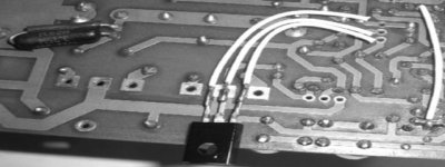
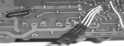
I've also attached a couple pictures that should help clarify number 8 and 9 of the Assembly Instruction section of the attached document.
For those unfamiliar with MikeB's SymAsym - The Sequel design, here's the link to the original thread.
http://www.diyaudio.com/forums/solid-state/87609-symasym-sequel.html
Here's the thread that I started describing my PCB design based on MikeB's design.
http://www.diyaudio.com/forums/solid-state/154717-my-new-symasym-pcb-design-rev_1-3-a.html
I still have a few boards left for those interested.
Regards,
Al
Attached is a pdf document with step-by-step instructions to help assemble my PCB. I'll provide transistor matching and testing instructions within the next couple days.
I've also attached a couple pictures that should help clarify number 8 and 9 of the Assembly Instruction section of the attached document.
For those unfamiliar with MikeB's SymAsym - The Sequel design, here's the link to the original thread.
http://www.diyaudio.com/forums/solid-state/87609-symasym-sequel.html
Here's the thread that I started describing my PCB design based on MikeB's design.
http://www.diyaudio.com/forums/solid-state/154717-my-new-symasym-pcb-design-rev_1-3-a.html
I still have a few boards left for those interested.
Regards,
Al
Attachments
So I see that the parts list is on Post 39 of the 'new' thread.
Post 45 of that thread says that cap C7/C8 are 15 mm not 10mm, so post 49 says to use mouser 505-MKP4-0.1/630/5.
Many of us want to order the correct set of parts so I think the first issue is to identify the latest schematic and parts list.
Using the above, is this the correct parts set to order?
Also, some of us (me) will want to put off-board diode bridges + big caps so is it just shorting out/ bypassing the on-board diodes or is there anything more complex?
Last edited:
So I see that the parts list is on Post 39 of the 'new' thread.
Post 45 of that thread says that cap C7/C8 are 15 mm not 10mm, so post 49 says to use mouser 505-MKP4-0.1/630/5.
Al confirmed the lead spacing for C7/8 are 15mm. I have checked mouser page: Mouser Part #: 505-MKP4-0.1/630/5 is equilvalent to Wima Part #: MKP4-0.1/630/5PCM15, so that lead spacing for this part is 15mm.
The Wima page also confirm the dimension & lead spacing: WIMA
- Stanley
Last edited:
Hi All,
Here the latest amplifier and power supply schematics plus BOM.
Igreen, I provided information noted below the PS schematic that should answer your question about using an External PS.
For the BOM I added Mouser part number 505-M10.1/250/10 which is a MKP10which according to the data sheets is better suited for audio equipment.
Thanks Stanley for pointing it out the different types of Wima caps.
I also added 3/8" nylon standoffs to the BOM used to mount the board to the main heat sink.
Regards,
Al
Attachments
Hi All,
Here the latest amplifier and power supply schematics plus BOM.
Regards,
Al
Hi Al,
Thanks for the updated schematics. I have not used any FETs before and I would like some advice on the JFET matching.
I only have a DMM and a single-channel handheld scope and a breadboard so I can only do basic device matching.
I found the following document from passdiy: http://www.passdiy.com/pdf/matching.pdf
The document mentioned: "Matching input MOSFETs is critical, because they must share equally the 10mA of bias current from the current source."
What is the normal bias current thru JFETs: Q1 & Q2?
To better match the following BJTs: Q5&Q6, Q9&Q12 and Q10&Q11, I would like to know their respective quiescent current.
Best regards, Stanley
first you must match at the operating currents that occur in the amplifier.I would like some advice on the JFET matching.
I only have a DMM and a single-channel handheld scope and a breadboard so I can only do basic device matching.
To better match the following BJTs: Q5&Q6, Q9&Q12 and Q10&Q11, I would like to know their respective quiescent current.
Second, the matching should still be reasonably good for a small range of current either side of the circuit operating current.
jFETs should be selected to have very similar Idss. But this requires three resistors and a 10V to 12V DC supply and an 8pin dip socket and consistent measuring procedure.
Then take a batch of similar Idss jFETs. Select one and make it your REF.
Select a DUT from the batch and thermally couple the two jFETs and insert them into the dip socket.
connect the gates pins together. connect the source pins together. connect the drains with identical 100r resistors to the +ve power supply ~10V for an Nchannel).
Connect the sources to the -ve power supply using a 200r resistor.
Connect the adjustable voltage, a pot, to the gate. Set Vgs to zero. Turn on the 10V supply. measure the voltage across each of the drain resistors. are the Vdrop the same. Then REF & DUT are passing the same current at Vgs=0.
Now adjust the pot to put -ve voltage on the gate. adjust until the Id is the operational current. Now measure Vdrop. are they the same? probably not. label DUT with the current difference from DUT.
Do this for each DUT.
Look for a pair of DUTs that have the SAME current difference from the REF.
Remove REF from the dip socket.
Insert the selected pair into the dip socket.
apply Vgs=0 and check these two have same Idss.
Now adjust Vgs to set Id to operating current. measure the ID of each jFET.
are they within the tolerance that you have set for matching?
you can easily find Idss within 0.1%. you can usually find Id within 5% @ operating current. If you can find a pair of jFETs that match to 0.5% over a range of 5 currents from Idss down to 20% of Idss then you have a supermatched pair. This will take 200 jFETs and 200hours to find a dozen or so supermatched pairs. If you set your tolerance to 1% you get a higher yield of pairs. You can increase your tolerance to 10% and you will find that almost all of your 200 jFETs can find a partner.
You do not need expensive equipment, you do not need absolute accuracy. You are comparing DUT to REF. This takes time and care and patience.
You can speed things up slightly by adding a CCS to the 200r resistor. This CCS should have a fixed current that matches two times the in circuit device quiescent current. This will require a higher voltage supply.
A similar procedure and similar jig can be used to compare small signal BJTs.
Last edited:
... I have not used any FETs before and I would like some advice on the JFET matching...
http://www.borbelyaudio.com/adobe/ae599bor.pdf (fig. 5)
http://www.borbelyaudio.com/adobe/ae699bor.pdf
Attachments
that measures Idss.
selecting matched Idss is of no value in a pair of devices that operate at a substantially lower bias current.
Hi Stanley,
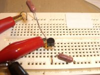
Attached is the circuit that I used to match Jfets Q1&Q2. I also attached a picture of my setup using a bread board. It's a simple circuit and works well.
On the matching circuit I set Idss to approx. 2ma, which is close enough to the actual current on the amplifier which is approx. 1.6ma. Use a DVM to check Vd on each Jfet and pair up the ones that match the closest. With 10 Jfets I was able to match 2 pairs pretty much right on. Of course that may vary depending on the batch sent.
For Q5&Q6, Q9&Q12, and Q10&Q11 matching hFE is good enough. The bias current across each transistor is about 3.25ma.
Best regards,
Al
Attachments
You might try a setup with a CCS. Basically, connect G to ground, D to the the same positive voltage you find in your application, and S trough a CCS to a negative supply (-10V or so). The CCS can even be a simple JFET CCS set to half the tail current in the input differential. Once you conenct your DUT, measure the voltage between G and S with a high impedance voltmeter (regular DVM will do fine). Match for the same voltage. This method is quite accurate but requires a dual power supply (+V, -V) - you can also use it to pair small MOSFETs, just insert a 1k or so resistor in the gate line to prevent oscillations.
Andrew's method is more accurate for finding pairs because it takes thermal coupling into account, though.
Andrew's method is more accurate for finding pairs because it takes thermal coupling into account, though.
It's not just the thermal coupling.
Testing/measuring as a pair allows Vgs to be equal, Vds to be equal (if Vdrop is equal), Id to be equal, Pq to be equal, Tj to be equal, Tc to be equal. All the things that are very difficult to control accurately are held equal. It's a real comparison of DUT and REF. When you find a pair, you know you have a pair.
Trying to find pairs or sets by measuring each individually leaves all the difficult to fix constants at haphazard values. There is no way to guarantee that the conditions for each single DUT are the same as any previous DUT, that day, that week, last year.
I have noticed that the device pair of DUT and REF can change if a door is opened and changes to cooling effect on one side that is different from the other side. No draughts is an important part of obtaining the equality during the testing.

I've been using the circuit in post #10 for years and works great. I found after doing some research that John Curl recommends a similar circuit for matching Jfets except he grounds the gate and source. I added a source resistor in order to drop Idss so that the jfets can be matched near their actual operating current.
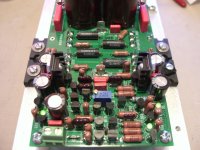
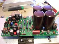
I've attached some pics of the new assembled board for reference.
Note the direction of Jfets Q1&Q2 is different that how it's labeled on the board. You'll find more information in my assembly instructions document found in Post #1.
Al
I've attached some pics of the new assembled board for reference.
Note the direction of Jfets Q1&Q2 is different that how it's labeled on the board. You'll find more information in my assembly instructions document found in Post #1.
Al
Attachments
Last edited:
Ordering Parts
The following parts are not availabe at Mouser (they are backordered), so lets talk substitutes.
I have given part numbers that I believe would be good substitutes, would these be ok?
Backordered
606-4300F1LC (L1, Red LED for + PS indicator)
substitute in
606-4300F5LC (use green instead of red)
651-1904383 (TB1, terminal block for Audio in)
substitute in
651-1872392 (2 pos labeled term block slightly higher profile)
71-RN60D-F-681 (R23, R24 681 ohms, 1/4 W, 1%)
substitute in
71-CCF55-681 (CCF series 681 ohms 1/4W, 1%)
505-MKS2-4.7/50/10 (C25, optional, Wima 4.7uF 50V metal poly cap)
substitute in
871-B32522C475J (Epcos poly film cap 4.7uf 63 V, not sure it fits).
Non Matching Parts.
Is part 757-2SC4793 really 757-2SC4793(F,M) ?
Is part 757-2SA1837 really 757-2SA1837(F,M) ?
EZ Buy / BOM Import
I have created the following EZ Order text using Al's part list.
Just click "EZ Buy" on the mouser page (at the top) and then the icon for the "BOM Import Tool." Paste the text into the window and the items will get added to your cart; do it 3 times for the 3 parts or all at once if you delete the "part" sections. Then you can remove the parts you already have/ don't want. The 3 sections correspond to the 3 pages of the .pdf parts list so you can follow along (EZ Buy does not let you put in user designators).
Part I
660-CF1/2C123J |4
594-5073NW1R000J |4
283-10K-RC |4
71-CW2B-10 |2
71-LVR3-0.20 |8
71-RN60D-F-22.1 |4
71-RN60D-F-10 |8
71-RN60D-F-100 |4
71-RN60D-F-150 |2
71-RN60D-F-150 |4
71-RN60D-F-261 |2
71-RN60D-F-10K |8
71-RN60D-F-681 |4
71-RN60D-F-22.1K |4
71-RN60D-F-2.0K |4
71-RN60D-F-499 |4
71-RN60D-F-1.0K |6
660-MF1/2CL68R1F |2
652-3296W-1-501LF |2
71-RN60D-F-221 |4
71-RN60D-F-10 |2
MKS2-.1/63/5 |18
661-EKMH630VNN472MQ |8
505-M10.1/250/10 |4
5982-10-500V100 |4
5982-10-500V220 |4
5982-5-300V10 |2
647-UVZ1J101MPD |8
647-UPW1E471MPD |2
505-MKS2-4.7/50/10 |2
Part II
863-MUR1520G |8
863-1N4007G |8
78-1N5245B |4
78-1N5235B |2
757-2SK170BLF |4
863-2N5551G |14
863-2N5401RLRAG |14
863-BC556BG |2
863-BC546BG |2
512-BD13916S |2
757-2SC4793(F,M) |2
757-2SA1837(F,M) |2
757-2SC5200-O(Q) |4
757-2SA1943-O(Q) |4
606-4300F1LC |2
606-4300F7LC |2
606-4300F5LC |6
534-1213 |10
651-1904383 |2
534-3517 |8
Part III
576-0217005.HXP |4
526-NTETP0006 |1
526-TP0010 |2
532-577002B00 |4
571-6409151 |10
534-29314 |8
561-K6.375 |8
No excuse for not getting moving on this now, right?
Last edited:
Mouser part no. for C7/8
505-M10.1/250/10 - Polypropylene Capacitors 250V .1uF 10% 6X12X13 - L/S 10mm (stock available = 4121)
505-M10.1/250/10P15 - Polypropylene Capacitors 250V .1uF 10% 5X11X18 L/S 15MM (stock available = 3)
The detailed specification for 505-M10.1/250/10 says that it has got lead spacing of 15mm, which contradict with its description, I suggest to call Mouser to clarify before ordering.
There is a Wima MKP10 capacitor of higher voltage rating, its lead spacing is also 15mm: 505-M10.1/400/5
- Stanley
I did an quick search on the mouser web by entering "505-M10.1/250/10" into the search box, it return two parts:Hi All,
For the BOM I added Mouser part number 505-M10.1/250/10 which is a MKP10which according to the data sheets is better suited for audio equipment.
Regards,
Al
505-M10.1/250/10 - Polypropylene Capacitors 250V .1uF 10% 6X12X13 - L/S 10mm (stock available = 4121)
505-M10.1/250/10P15 - Polypropylene Capacitors 250V .1uF 10% 5X11X18 L/S 15MM (stock available = 3)
The detailed specification for 505-M10.1/250/10 says that it has got lead spacing of 15mm, which contradict with its description, I suggest to call Mouser to clarify before ordering.
There is a Wima MKP10 capacitor of higher voltage rating, its lead spacing is also 15mm: 505-M10.1/400/5
- Stanley
all is not lost.
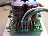
C7 C8 are 15mm pin pitch. If you cannot source this size, a 10mm can be made to fit the PCB.
Look at the photos of the back and front of the PCB.
An extra hole can be drilled in the power trace 5mm from the existing hole.
Then a 10mm pin pitch cap can be made to fit.
C7 C8 are 15mm pin pitch. If you cannot source this size, a 10mm can be made to fit the PCB.
Look at the photos of the back and front of the PCB.
An extra hole can be drilled in the power trace 5mm from the existing hole.
Then a 10mm pin pitch cap can be made to fit.
- Status
- This old topic is closed. If you want to reopen this topic, contact a moderator using the "Report Post" button.
- Home
- Amplifiers
- Solid State
- SymAsym - "The Sequel", AAK's PCB Builders Thread