Hello all,
I'm an earnest noob trying to learn theory and practice while keeping my aging system running. I have good mechanical skills, but only rudimentary knowledge of testing and troubleshooting. I've been reading and studying theory, but have a long way to go.
My faithful GFA-555 couldn't wait for me to get studied up. It's blowing the fuse on the left Output Board II and that channel has 82vdc at the speaker out! (The good channel was a respectable 41mvdc, btw).
After reading many threads here, there and everywhere, I pulled that board and tested Q11 (the driver transistor, right?). It passes the diode test. My DMM can measure HFE, but I'm not sure what I'd be looking for. (I said I was a noob.) If I replace it, am I correct that it does not need to be matched to Q12?
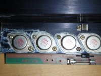
A more experienced acquaintance recommended I look first for blown output transistors, and the ones on this board do look a little suspect with all the drippy thermal grease running down (see attached). There was also a little greasy, sticky spot at the bottom of the case below this heatsink. The other heatsinks are much cleaner looking with no grease spots.
There are no other obvious burnt, bulging or cracked parts on this board or the front end board.
I reckon my next step is to remove and check these transistors (Q13-16)? If one or more is bad, it's my understanding I would have to replace all four with matched pairs to Q17-20.
Any and all help is greatly appreciated.
I know I'm asking a lot here. I know it's a questionable undertaking to try and repair something you don't really understand. As a bike mechanic (back in college) it always bothered me when people assumed it was simple to perform a given procedure. But I don't have many options for getting this puppy fixed, and I miss my music, so I throw myself on the mercy of the Internet.
I'm an earnest noob trying to learn theory and practice while keeping my aging system running. I have good mechanical skills, but only rudimentary knowledge of testing and troubleshooting. I've been reading and studying theory, but have a long way to go.
My faithful GFA-555 couldn't wait for me to get studied up. It's blowing the fuse on the left Output Board II and that channel has 82vdc at the speaker out! (The good channel was a respectable 41mvdc, btw).
After reading many threads here, there and everywhere, I pulled that board and tested Q11 (the driver transistor, right?). It passes the diode test. My DMM can measure HFE, but I'm not sure what I'd be looking for. (I said I was a noob.) If I replace it, am I correct that it does not need to be matched to Q12?
A more experienced acquaintance recommended I look first for blown output transistors, and the ones on this board do look a little suspect with all the drippy thermal grease running down (see attached). There was also a little greasy, sticky spot at the bottom of the case below this heatsink. The other heatsinks are much cleaner looking with no grease spots.
There are no other obvious burnt, bulging or cracked parts on this board or the front end board.
I reckon my next step is to remove and check these transistors (Q13-16)? If one or more is bad, it's my understanding I would have to replace all four with matched pairs to Q17-20.
Any and all help is greatly appreciated.
I know I'm asking a lot here. I know it's a questionable undertaking to try and repair something you don't really understand. As a bike mechanic (back in college) it always bothered me when people assumed it was simple to perform a given procedure. But I don't have many options for getting this puppy fixed, and I miss my music, so I throw myself on the mercy of the Internet.
Attachments
First question I have is, is this really a GFA-555, or is it a 555-II?
Reason I ask is that I have a 555-II that came to me with 80V of DC at the output, and it's common on those amps, and has to do with bad pre-driver transistors on the input board.
However, my amp wasn't blowing fuses. If you're blowing fuses without a load hooked up to the amp, then you probably have blown output transistors on one rail. The quick check would be, on the output transistors of the bad channel (with the amp off and fully discharged), check resistance from collector (case) to emitter on the two polarities of output transistors. This should be very high (many K Ohms). You can compare to the working channel for a reference of what a good reading should be. One polarity of transistors is NPN and will have numbers starting with 2SC or 2SD or C or D. The other ones will be PNP and will have numbers starting with 2SA or 2SB or A or B. All the output transistors of the same polarity are connected together in parallel, so you only need to check one of each polarity on the bad channel to see whether the resistance is reasonable or not.
(Edit: Just looked at your picture and saw the 2SB554 designations. These would be the PNP output transistors. The NPN ones will be marked 2SD424. This also answers my question about whether it's a 555 or 555-II... it's a 555.)
I expect you'll find one or both polarities where the resistance is < 1 Ohm. That will indicate that one, or more likely all, of the transistors for that polarity are shorted. If that's the case, they will need to be replaced, and further testing will be needed to see whether there are other devices further up the chain that are also damaged.
Let us know what you find in your tests.
BTW, under what circumstances did the amp fail? Was its output shorted accidentally or hooked up to a bad speaker?
Cheers,
Paul
Last edited:
Oh, in more direct response to your other questions:
1. No, you don't need to remove the output transistors to check them, unless you find that one or more are shorted... then you'll at least need to isolate them enough to see which ones are shorted.
2. No, matched devices aren't required, as the emitter degeneration resistors will force current sharing for the output transistors. Matching won't hurt, but it's not critical. Suitable substitute output devices would be On Semi MJ15022G and MJ15023G. If you buy them new, from On or Mouser, etc, they should come from the same lot number and be reasonably similar in behavoir even unmatched. Companies like Tech-DIY sell matched sets of transistors, but I don't see that they carry the 15022's and 23's.
Cheers,
Paul
You don't need to remove the transistors to find the shorted device but you need a VOM that reads reliably to less than an ohm. Measure the E-C resistance on each of the transistors. The good ones will read a short (the bad one) plus the 2 emitter resistors. According to my GFA-555 book that would be 0.82 x 2 while the shorted one will read 0. Remove the bad one and check the other group of 4 outs. This simultaneously verifies the emitter resistors as being good. If any transistor reads more than 2 ohms you better check the emitter resistor on that device. I've never seen 2 devices in parallel fail but almost always 1 in each group in series between the power rails. When you've removed the bad transistor on the other leg (positive and negative supply rails, it is safe to power it up with the fuses in. It should not be blowing fuses and the DC output should be nominal +/- 50mV. You can run signals into it with no or light load and check the output with a scope. Shut it down and replace the missing transistors. I agree with SQLGuy's OnSemi suggestion but I would not mix part numbers in a channel. IOW, all Toshibas or all OnSemis in a channel.
Happy New Year
G²
Happy New Year
G²
Hi all,
Many, many thanks for replies.
So if I'm understanding correctly, in order to do the tests suggested by Paul and G2, I need to re-mount Q11 and then re-mount/re-connect the board back in place in the case. Unless there's another way to test the transistors with the board un-mounted/disconnected?
FWIW, with the board removed, measuring across E-C of Q13-16 read 8.9 MOhm (and 180 MOhm with the test leads reversed, C-E).
Thanks again for the help, guys.
Okay, I'm starting over. I reassembled and reconnected everything. I installed a six-amp fuse. Plugged it in and turned it on, with no load, no input (I know, I need a variac). The good channel still has 41 mvdc and the bad channel still has 82 vdc. The fuse did NOT blow. In the interest of science, I tried a 5 amp fuse and it did not blow either.
After I had initially found the blown fuse, I had just replaced it with a 5 amp (all I had) and put it back in my system. The fuse blew again almost immediately. So I think I can say that it's only blowing fuses under load. I do have some 100w 8ohm resistors I could use for a test load, if that would be safe.
As I said, I don't know for sure if there was speaker wire short, but it's possible. The speaker that it was connected to has no faults and plays fine.
More data:
Amp fully assembled, not grounded, not powered.
I measured resistance across C-E in all the output trannies, (the Toshiba 424's and 554's) in both channels. First I measured C+/E- then I switched the test leads and measured C-/E+. I averaged the results for each group of four since they were all very close (as expected since they are in parallel, right?). Here's what I got:
Good Channel:
424's:
C+:123.3 kOhms
C-: 193 kOhms
554's:
C+: 120.8 kOhms
C-: 219.5 kOhms
Bad Channel:
424's:
C+: 52.6 kOhms
C-: 96.3 kOhms
554's:
C+: 56.1 kOhms
C-: 106.6 kOhms
So the values in the bad channel are roughly half what they are in the good channel, indicating something else is open?
All the fuses installed, none blown out and you get 82 V output, stable? IF that's the case, none of your outputs have failed. You have a problem in the voltage amplifier portion of the amp, Q1 through Q8. It might _not_ be a semiconductor failure but could be an open (rare) or shorted (very rare) resistor. I have seen ceramic caps that go leaky or short out, (rare) and same for 'lytics (rare). You'll need to see if the current sources Q3 and Q4 are functioning by measuring the voltage drop across R14 and R16. i would expect these both to be around 700mV but BE CAREFUL when measuring these as they are on the -82 V rail. NO FAT PROBING!!! If this was my amplifier I would measure all the forward and reverse junctions of Q1 - Q8 and since I have a curve tracer, I would verify all functioning normally.
G²
G²
Hi G2,
thanks for the response. Sorry to be such a noob, but how, exactly, would I measure the "voltage drop across R14 and R16"? Do I need to connect a load to the amp? Or do I just turn it on and measure voltage across each of those resistors? Similarly, can you explain what you mean by "measure the forward and reverse junction of Q1-Q8"?
Sorry to be so ignorant. All I can say is, at least I know I'm ignorant and trying to fix it!
cheers,
Fred
I have a gfa-555 as well and had the same problem. One of my friends found a bad ristor and replaced it, I have had that amp for some time now and no probs,, if you need pics of the repair, PM me and I will try and show the repair. I am a noobb as well, but i still love m adcom amp.
The question then is, what's a "ristor"? I would guess that's short for resistor, but resistors by themselves very rarely go bad. They are generally damaged when a nearby transistor fails.
BTW, the A1210's, and C2912's, should be small transistors on the input board, in positions like Q4 and Q7.
BTW, the A1210's, and C2912's, should be small transistors on the input board, in positions like Q4 and Q7.
Hi Paul,
Sounds like you and G2 are on the same page, except for the testing. I'll do the diode test on A1210 (Q7) and the C2912 (Q4) first, since that sounds safest (both for me and the amp), and then I'll see if I can figure the right way to test the voltage drop across the resistors as G2 suggested.
I can test Hfe on my meter. Would it be more accurate/helpful to pull these trannies and test them out of circuit?
Hi G2,
thanks for the response. Sorry to be such a noob, but how, exactly, would I measure the "voltage drop across R14 and R16"? Do I need to connect a load to the amp? Or do I just turn it on and measure voltage across each of those resistors? Similarly, can you explain what you mean by "measure the forward and reverse junction of Q1-Q8"?
Sorry to be so ignorant. All I can say is, at least I know I'm ignorant and trying to fix it!
cheers,
Fred
What I mean is measure the voltage on R14 and R16. You would place a probe (meter lead) to each end of one of the resistors and note the value and then measure the other resistor. As I said I'd expect about 700mV. Keep in mind the resisters are at -82 volts so you don't want any 'accidents' to damage more than is already bad.
I don't believe this failure was caused by anything you did like shorting speaker cables.
G²
- Status
- This old topic is closed. If you want to reopen this topic, contact a moderator using the "Report Post" button.
- Home
- Amplifiers
- Solid State
- Another high DC Adcom GFA-555