I haven't posted in quite awhile. I thought maybe someone besides myself could use this.
Maybe someone can tell me why these amps are notorious for ear shrieking treble gain.
An externally hosted image should be here but it was not working when we last tested it.
Maybe someone can tell me why these amps are notorious for ear shrieking treble gain.
Last edited:
don't know if i can answer your question, seeing as i don't recall ever listening to one of these amps. however, i'm puzzled by something i see on the schematic: regarding the diff amp input parts, (2SA798 and 2SC1583), i thought those were 5 pin devices that did not offer access to the individual emitter connections, so i'm wondering how/if those 10 ohm emitter degeneration resistors are really connected.
mlloyd1
mlloyd1
Q5/Q12 would protect the VAS from current overload if a VI limiter triggered - there isn't one shown on the schematic though.
I think most of the reason for the treble gain you speak of is the relatively low amounts of bias the Acurus products are set for. I would think that upping the bias voltage beyond the factory specs, as long as the heatsinks can handle it, would help to alleviate this. The addition of some CRC filtering in the power supply couldn't hurt either.
Here is the Mondial bias voltage setting for their products. Interestingly enough the Aragon 004 series original bias setup procedure says to set them for 10 mv and not the 6-8mv that this procedure calls for.
Here is the Mondial bias voltage setting for their products. Interestingly enough the Aragon 004 series original bias setup procedure says to set them for 10 mv and not the 6-8mv that this procedure calls for.
Attachments
I think most of the reason for the treble gain you speak of is the relatively low amounts of bias the Acurus products are set for. I would think that upping the bias voltage beyond the factory specs, as long as the heatsinks can handle it, would help to alleviate this. The addition of some CRC filtering in the power supply couldn't hurt either.
Here is the Mondial bias voltage setting for their products. Interestingly enough the Aragon 004 series original bias setup procedure says to set them for 10 mv and not the 6-8mv that this procedure calls for.
I have not heard this with regard to other amps with similiar problems.
I was not aware that an increase in bias current will affect frequency issues.
I am open to trying this. Where am I measuring the 6mv at or across???
Increases in bias voltage have many times been attributed to a warmer sound, not to mention it warms the heatsinks up and subsequently your room. 🙂
The voltage readings are taken across the emitter resistors (.5 ohm/2 watters). If you do not have a way to measure the heatsink temps, if you can hold your hand on the thicker baseplate area of the heatsink you are probably okay.
The voltage readings are taken across the emitter resistors (.5 ohm/2 watters). If you do not have a way to measure the heatsink temps, if you can hold your hand on the thicker baseplate area of the heatsink you are probably okay.
Ahhh, ok,
After a long warm up, the amp has been on all day. I read 2.3mV on one channel and 3.1mV on the other. Probably not good.
I have adjusted the bias as advised and now have 6mV on both channels now.
I will periodically check the bias over the next 24 hours and then screw the top back on.
Chamberman, thank you, again, for the bias info!😀
Wow that is low. Definitely keep an eye on the temps. Its possible your meter reads a little low too! The heatsink temp will tell you if your getting too high on the bias. You'll have to report back on how it sounds after the change.
Hags, I am interested in something. I have a schematic of the A250 and it is a clone of the one you posted. Even the rails are the same +/- 85 vdc. Did you ever measure the rails on that thing. I'm interested in whether they are in fact +/- 85 vdc. I'm thinking that the A200/A250 amps are the same with the only difference being the rail voltage. I'm guessing the rails are probably really +/- 70 vdc on the A200, this would match up with the Aragon 8000 series which put out 200 watts per channel and used very similar circuitry.
Last edited:
I did in fact measure the rails, the rails on my A200 are at +/- 73 Vdc. I thought that was a little high as the PSU caps are rated at 85 Vdc.
I was surprised as the rails on my NX-150 amp are 63 vdc and it subjectively has much more command of my speakers.
In addition to resetting the bias I have removed the stock rectifier bridge and components and installed a Pers-Anders RFB02 rectifier bridge. The (positive)effects of the RFB02 were immediate and pronounced.
That doesn't surprise me that the circuit is similiar to the Aragon.
The Acurus amps are not bad amps. Certainly much better than the ATI 1502, various Adcoms, B & K among others.
With the bias is at a rock steady 6.4mV and the addition of the RFB02 the ear shattering highs are gone. The frequency response has really smoothed out and I no longer want to shut it off after 10 minutes.
Stick definition on cymbals is more precise and along with cymbal wash is more realistic than they were before the bias adjustment. Now I know!!!!
Okay, 73 vdc rails that makes sense. Yea, 85v caps do not leave a lot of headroom. If you plan on CRC'ing the power supply I would buy some 100V caps and put them on the bridge side of the CRC filter. You could at least take a little voltage off of those 85V caps that way.
It looks like the biggest difference between the 8000 series aragon amps and the acurus amps was in the power supply. The aragons had a massive PS in them. But they both used the same output devices and the circuitry was very similar. Here is one of the 8000 series schematics if you'd like to check it out. 🙂
It looks like the biggest difference between the 8000 series aragon amps and the acurus amps was in the power supply. The aragons had a massive PS in them. But they both used the same output devices and the circuitry was very similar. Here is one of the 8000 series schematics if you'd like to check it out. 🙂
Attachments
Okay, 73 vdc rails that makes sense. Yea, 85v caps do not leave a lot of headroom. If you plan on CRC'ing the power supply I would buy some 100V caps and put them on the bridge side of the CRC filter. You could at least take a little voltage off of those 85V caps that way.
It looks like the biggest difference between the 8000 series aragon amps and the acurus amps was in the power supply. The aragons had a massive PS in them. But they both used the same output devices and the circuitry was very similar. Here is one of the 8000 series schematics if you'd like to check it out. 🙂
Yes, very similiar. The differences I can see are 1) the Aragon is a dual mono supply and 2) it has 35,000uf per rail per side instead of the 23,000uf per rail in the Acurus.
I've got 100 V caps in my DIY amp and that only has 63 volt rails. Who knew I could cheap out with 80 volt caps?!?
I wouldn't mind beefing the PS up but there is really no room. They have the PS caps mounted horizontal to save space in the A200.
The ultrafast rectifiers and snubbers I used in the RFB02 and maybe some bypass caps on the PS reservoir caps and that'll be it for the PS I think.
I see the Aragon uses the same thermistor as the Acurus, ha,ha.
Hello, and thank you for the schematic. I've had an A250 since 1992, and maybe this will finally get me to open it up and turn up the bias. I remember writing on the warranty card: "This amp runs cold! Wouldn't it sound even better if the outputs were biased a little hotter?" Thanks also to Chamberman for verifying that this schematic is the same as the A250. I noticed, as I'm sure you did, that the Aragon is DC Servo coupled, as opposed to the capacitor coupling of the Acurus. It wouldn't take much to add the servo; wouldn't that be fun?
Thanks again, to both of you.
Bert
Thanks again, to both of you.
Bert
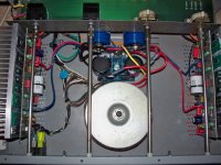
I recently did a huge upgrade on my Acurus DIA100. I added Fairchild Stealth II soft recovery diodes and a CRC filtered PS. I also pulled the main amp pcb's and replaced all of the Wima MKS polystyrene caps with MKP polypropylene caps. I also replaced the 10uf electrolytic input cap with a 10 uf MKP film cap. In doing some research on the Aragon series of amps I noticed that Mondial used electrolytic/film caps inboard of the rail fuse to bolster the PS at the transistors. This also has the added benefit of using the resistance inherent in the fuse as an additional CRC filter stage. I went ahead and modded the pcb to include a 47uf Nichicon FW audio cap and Wima MKP for each rail on the pcb side of the rail fuse.
I also replaced the single turn bias adj pots with multi-turn units. The old single turn pots were so touchy that you just breath on them and the bias would move. Now I have to make a 1/2 turn adj to even get the bias to move, much nicer! 🙂 One other change I made was to replace the cheap 18 ga power cord with a good 16 ga cord. I also added a foot to the length of it to give me some more placement flexibility. I was really shocked to see an 18 ga cord on a power amp of this quality. The 16 ga cord would have only cost Mondial a few cents more and even if it makes little difference to the power output it at least looks better.
The results after the changes were quite startling. I had previously bumped the bias up to 10mv and that made an impressive difference in sound quality. My DIA100 was set for 2mv of bias, pretty weak really, but it had probably drifted down over the years I'm sure. Even at 10mv of bias, the heatsinks get only mildly warm to the touch after an hour of reasonably loud playback with the cover on. But the change in sound quality after the parts replacement blows the bias change away.
The changes after the pcb mods and PS mods were amazing. The bass seems to go a full octave lower than it did before. It has way more punch even at low volume levels. The sound also has much more air to it and seems much cleaner and more relaxed. The amp can go louder without breaking up or getting irritating to listen to as well. FWIW I owned an Aragon 4004 MKII and an 18K back in the mid 90's for about 5 years. I bought them brand new and had them hooked up to a set of B&W Matrix 804's. I think my modded DIA100 with an old CAL CL-25 disc player feeding it sounds better than that old combo did.
Here is a pic of it after the mods.
Attachments
One other thing.
I recently purchased a defunct A200X3, I got lucky and it only had a couple of blown rail fuses, I replaced them and its now up and running again. I noticed the PS caps were 23,000uf/95 vdc units. I got my meter out and sure enough the rails are +/-82 vdc. The A200X3 uses the higher voltage PS from the A250. I'm saying this based on hags earlier observation that his A200 has 85 VDC caps and +/- 73 VDC rails. I also recently saw a picture of the internals of an A200, the transformer is obviously smaller in diameter than the one in the A200X3.
This makes sense, Mondial rated the A200X3 as 200wpc with 3 channels driven. The added load of the 3rd channel meant that the A250 PS could only deliver 200WPC into all 3 channels. So what does this mean? When in stereo mode the Acurus A200X3 is nothing more than an Acurus A250, the circuitry is identical... Anyone looking to purchase an A250 might want to think about an A200X3. The prices are just about the same and you have another channel to use and a slightly taller chassis which means there is more room to add mods if you so choose. The cool thing is that all 3 amp pcbs/heatsinks are the same. So even if you use it as a stereo amp, if you ever lose a channel, just swap to the 3rd channel and go! Its like having built in spare parts, not that you would ever need them. 😛
Last edited:
Why not implement a DC servo?
Remove the input cap and the feedback cap and implement the DC servo as shown in the 8008 schematic posted in this thread. The A200 schematic attached is hard to read. It may have +/- 11V take off points for the servo VS 12V for the 8008.
Remove the input cap and the feedback cap and implement the DC servo as shown in the 8008 schematic posted in this thread. The A200 schematic attached is hard to read. It may have +/- 11V take off points for the servo VS 12V for the 8008.
Hello, first time post. I am not an engineer but a friend of mine is and he is going to help me with this project. I am trying to get a few bits of info to start modifying one of 2 a250's I just purchased. One is hooked up right now and driving a pair of KEF Reference two speakers. They are a 4 ohm load which drops to 3 ohm under 150hz. the can be hard to drive. I bought these off a local guy who was the original owner. They are mint. I am using one to replace my adcom 545II which just didn't have the *** to drive the Kefs like these do. My plan is to take one and make a few changes at a time and see how it compares to the unmodified one.
Starting with the power supply side I want to add bypass caps and the Pers anders rectifier. Is there a place to buy this rectifier. Also, the caps in the one I have open are not Cornell Dublier as mentioned to be in these amps. They are GE electrolitics and from what seems to be 1992. Should I upgrade these and if so, what is a good brand to use in a higher rating that might still fit the brackets.
that is where I am at so far. researching more while typing this.
Thanks
Mike
I haven't posted in quite awhile. I thought maybe someone besides myself could use this.
An externally hosted image should be here but it was not working when we last tested it.
Maybe someone can tell me why these amps are notorious for ear shrieking treble gain.
All amplifiers in this topology and this selected values for idle currents in the LTP and VAS stage sounds for me in the same kind, as you say.
A significant reduction of this unwanted sound effect you will get by enhance the idle current for the LTP from 1 mA to 5 mA for each half (each transistor of differential amp) and replace the current mirror through ordinary resistors. Additional helpful is the introduce of a buffer stage between LTP and VAS stage (blameless amp from Douglas Self).
But please note - to perform this redesign, a P-Spice simulation tool (like LT-spice) is absolutely necessary, because the compensation caps must get new values and sometimes new places.
Here an another great lack: behind the protection fuses in the pos and neg. rail are no caps. This make the sound also extremly worse (also often to find in a lot of other models).
Last edited:
- Status
- Not open for further replies.
- Home
- Amplifiers
- Solid State
- Acurus A200 schematic here