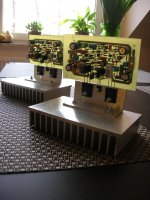
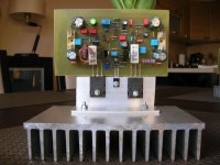
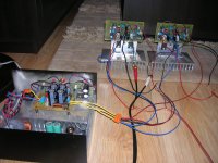
Good Luka...but i have found more stable boards oversized
20 to 25 percent bigger... this create some troubles to capacitors distance..but i could see, tests made today, the bigger one is much more stable than the official board.
So, i suggest you to increase your boards size prior to building.
I have some tricks to unstabilize circuits, and i see the bigger one is hard to unstabilize, when the official sized board is easier to unstabilize.
Thank you Luka....nice picture...nice evaluation.
I will suggest you not to tweak bias...better to keep it the way it is..just check if you have current in the power emitter resistances, and if you have more than 500 milivolts from base to emitter in the power transistors.
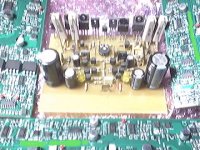
Luka coil style is better..i found the coil is coupling to the input...i have shield and i felt strange superimposed signals above 500 Kilohertz have disappeared.
Luka pictures posted....Luka from Polland, the previous post.
regards,
Carlos
20 to 25 percent bigger... this create some troubles to capacitors distance..but i could see, tests made today, the bigger one is much more stable than the official board.
So, i suggest you to increase your boards size prior to building.
I have some tricks to unstabilize circuits, and i see the bigger one is hard to unstabilize, when the official sized board is easier to unstabilize.
Thank you Luka....nice picture...nice evaluation.
I will suggest you not to tweak bias...better to keep it the way it is..just check if you have current in the power emitter resistances, and if you have more than 500 milivolts from base to emitter in the power transistors.
Luka coil style is better..i found the coil is coupling to the input...i have shield and i felt strange superimposed signals above 500 Kilohertz have disappeared.
Luka pictures posted....Luka from Polland, the previous post.
regards,
Carlos
An externally hosted image should be here but it was not working when we last tested it.
Attachments
Last edited:
This amplifier is not entirelly stable, nor reliable
URGENT MESSAGE...ATTENTION PLEASE!
I am conducting a series of testings, in all my Dx Blame ES amplifiers...and i found it critical in values...it easy goes from stability to oscilations, depending levels and how high are the frequencies entering.
I would like to apologize, but i perceive that very latter, maybe this was what Eva was intending to tell me.
I did my best, and for sure this is the most lovely amplifier i have made...the best wide world amplifier in sonics..but we pay for that....it shows small signs or unstability, and you may face fuses burned because of that.
In these 15 amplifiers built, 3 have faced troubles with bias....this is a very big percentual.
I have to apologize to Rudi, to Ekkart (Volker), to Luka, Funky2x and my close friend that have assembled...they are happy because sonics, but i cannot guarantee they will not face troubles near future.
Boards expanded in 25 percent are much more stable,but capacitors will have wrong distances between leads and board will result very ugly too.
Boards are not the main problem, it seems to me the circuit is unstable, and was unstable since the early beginning (see thread in the early beginning)...i have made all i could.... also i had the belief it was stable...but even the unit i use daily, when i increased equalizer 24 dB in the treble range, then he blow up fuses.....and fuses were correct ones...was oscilation....so.... working for weeks without problems...one day the unit oscilated.
The ones have built...INSTALL URGENTLY FUSES IN THE OUTPUT TO PROTECT YOUR SPEAKERS.
I wil continue to use, as i never have listened so good power amplifier, will fix if mine units blow up...maybe i will find a good solution.... the one i found, with the "avant première" version, the solution i found, killed sonics...so..it is not the good solution.
In the name of decense, to be honest, i do not suggest you to build anymore...do it under your own risk... and accept my humble apologizes.... you have the best i could make.... i really think it is the best wide world amplifier in sonics..but sadly, it is not perfectly stable, not too much reliable.
Build the Dx Amplifier, the Dx standard...this one will never produce surprises to you.
Sorry boys.
regards,
Carlos
Last edited:
We all know .. You doing and did . Thank you
Big thank to you Dear Carlos for all the effort you made to put this amp into work and the help you gave me and other members .
In my point of view ..
after assembled the first amp ( two channel ) and what happened with me .
the first thing came to my mind about the loose in components value I found later when did the components measure .
My doubt was there and why that loose in the value .
the first Amp .. sound was Fabulous ... clear .. punch of bass ( yes I had that much enough to shake the building )and the impressive Treble was there too .
then .. three to four days later happened that the second channel stopped from working and the did the same thing ( measuring components and there was also a loose in the value ) is this a normal thing to happen ?
after assembled this working one . i tried to pick up value as much as close according to the schematic ..
like 220 Ohm ... did with exact 220 Ohm no minus no plus .
To be honest ... I like the first one assembled ..
when turn the volume high ( not too much ) and increase the bass .. there is like a distortion in the sound ... But I like it . Still .
Well .. was busy to post here and that why am late doing from time to time .
so , am going to follow the steps you mentioned and will see .
I do like the DX standard .. but this one is a MUCH .")
things can happen .
Big thank to you Dear Carlos for all the effort you made to put this amp into work and the help you gave me and other members .
In my point of view ..
after assembled the first amp ( two channel ) and what happened with me .
the first thing came to my mind about the loose in components value I found later when did the components measure .
My doubt was there and why that loose in the value .
the first Amp .. sound was Fabulous ... clear .. punch of bass ( yes I had that much enough to shake the building )and the impressive Treble was there too .
then .. three to four days later happened that the second channel stopped from working and the did the same thing ( measuring components and there was also a loose in the value ) is this a normal thing to happen ?
after assembled this working one . i tried to pick up value as much as close according to the schematic ..
like 220 Ohm ... did with exact 220 Ohm no minus no plus .
To be honest ... I like the first one assembled ..
when turn the volume high ( not too much ) and increase the bass .. there is like a distortion in the sound ... But I like it . Still .
Well .. was busy to post here and that why am late doing from time to time .
so , am going to follow the steps you mentioned and will see .
I do like the DX standard .. but this one is a MUCH .
things can happen .
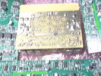
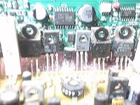
You should not have ignored my advice, now you are probably where I was 10 years ago. Take a look at the pictures, compare my 10 year old DIY work covered in dust (similar to yours, see BD139 and BD140) with my current work for the professional audio market.
10 years ago I had trouble finding and solving parasitic oscillation and cross-conduction issues in class AB output stages, I feared these problems. Now I design switching amplifiers whose working principle is controlled instability, my preferred ones
10 years ago I had trouble finding and solving parasitic oscillation and cross-conduction issues in class AB output stages, I feared these problems. Now I design switching amplifiers whose working principle is controlled instability, my preferred ones
Attachments
What i mean with the word unstable.
In one moment behave fine, next moment do different.
Normal use, standard recordings alike MP3 320K, then nothing happens...plays fine..but when you use high quality recordings, alike the Flac ones Rudi sent me from Germany..then things appears.
Recordings where you have high levels of treble.... loud high frequencies, then you perceive, from time to time something distorting in the loud high frequency tones, during peaks..but fast recover when normal levels are playing.
While adjusting my meter, a VU meter, to read precisely the power...then i tried high levels of bass, a steady tone in low, mids and highs to see my meter movement..also i have switched these tones on a off to see how fast meter would move..to see he average measurement... the meter has small capacitor but after diode bridge...audio is captured in the output, having 1k in series..so...this is not loading the amplifier...load was 7 ohms inductive resistance..some microhenries there...maybe 70 microhenries.... the unstability happend with other loads too, also without the meter...... well, while adjusting i decide to see how the VU would behave with 20 kilohertz full sinusoidal power.....MAN!.... the oscilation came when reaching the threshold of clipping...and them the amplifier burns first time...my home constrution, the one was playing since last Christmas.
Then i did this same test using the standard boards, the official boards.... i had fuses burned..this time nothing happened with the output.
I tried with the enlarged board...and nothing happened, not even transistors burned or fuses...but i could see some small signs of oscilations, the lost of synchronism in my scope..that unstability in the scope waveform shows that something is not fine.
Back to my point to point board, i have replaced the output and drivers... all them shorted...have changed capacitors, removed C18 and other small modifications..... increasing power.... then burned once again... this time VAS transistors (2), drivers and output gone.
This repeated four times...them i dismounted the whole amplifier...cleaned the board, inspected using magnified lenses, all parts replaced, the original official schematic used....assembled entirelly and then i have made the same test once again...... i could reproduce 500 Kilohertz..perfect waveforms...good square wave till 40 kilohertz... the i switch the whole thing off and went out for food shopping..when back home, tried once again to adjust meter..the meter was connected previously (do not blame meter, it is fine, not loading)... oscilated and burned output once again, and one driver, this time the NPN one.
I have replaced drivers by TIP41 and TIP42, as they do not oscilate easy...they cannot oscilate high frequencies because they do not work in high frequencies, they have enormous losses..... even this way the whole amplifier burned..gone VAS (2), gone drivers and output power.... nothing happened in the input..never burned any input transistors.
The garbage basket was filled with several transistors, and 10 expensive power units burned, shorted there.... i decide to inform you, and to suggest you not to build anymore..also i did that to my Orkut friends..they have complained, they said their units are lovely, working great..i said it is not stable... they may face surprises near future..... that i was unable to find a good solution without destroy sonics...the "avant première" version published does not oscilate, anyway..but sound is AWFULL.... and this is not a good solution.
You may say..... you are already thinking:
- " No one will have full power in 20 kilohertz!... this usually is not present in music..why to bother about this Carlos?"
Listening ordinary, average quality music, no problems...but if you use your amplifier together a mixer, and them a microphone starts to produce microphonic feedback sound, with enormous content of high frequencies..then a shame to you...the party will over.... the amplifier will burn!...this is not a good thing to happens...so... you are informed.
I am very sorry dear Luka, also dear Rudi,.... Funky and others.... a beautiful amplifier, with unbeatable sonics...but dangerous, my obligation is to inform you that in a such way you will have not more doubts..if you decide to insist, to build and to listen, at least you know the risks...install fuses, or you will burn speakers.
I will be listening...no more 20 kilohertz full power....but knowing that i can have surprises...my own decision, my own risk.
Maybe other amplifiers will burn under the same conditions.... well, others are not my problem, they are not Dx Corporation amplifiers, made to my friends..with the guarantee of reliability.
Will i continue to research?...OFF COURSE...will never give up...just a break to breath some fresh air... those power units burned are a pain in my heart... i need to take some time to myself, prior to return to the workbench.
Simulator says nothing.... a hell thing..... do not shows sonics and do not show problems...simulators have error correction.... aaaagh!
A perfect simulating amplifier, super stable in the simulator, a top performer...distortion bellow 0.002 percent.... a time bomb in real life!
All Dx Blame ES advertising, vídeos in Youtube were deleted.... my personnal friends in Orkut were informed, and asked to stop building....it is up to them if they want to take the risk to build the best wide world audio amplifeir.... maybe they want (I want!) even knowing the hell thing may explode!
Suggestions wanted...i cannot promisse i will try all them, as i have tried, probably, 90 percent of possible suggestion contents related modifications... combinations of modifications goes to infinite...this means ethernal work...and this is not something i am decided to do... to stay all my life trying each suggestion...i will read and will try some of them.
You may help too....but take some job to yourself....design, build, test and listen,,,,this will be a real help....much better than go suggesting things for me to do....this may be easy to you....but not easy to me as represent to be sitted for a lomg time when i have not health to face that....simulator things or calculated things are not a good help....the do not represent real world...they are just thesis.
regards,
Carlos
Last edited:
Carlos,
Look at this maybe it helps to find the solution http://www.diyaudio.com/forums/solid-state/112426-hexfet-amp-please-help-me-fix.html
Look at this maybe it helps to find the solution http://www.diyaudio.com/forums/solid-state/112426-hexfet-amp-please-help-me-fix.html
The schematic in post 827 has many things calling for hard to predict trouble (like layout/signal/transistor-brand dependent oscillations), I already gave you a list some time ago.
The most dumb thing about that circuit is probably C24, followed by C25, C17 and C15.
C25 without series resistor can cause local VAS instability (Q6/Q7/C13 loop).
C12 can cause local Vbe-multiplier instability without a series resistor (bias can go crazy, for example when the amplifier clips).
C18 can result in resonance and bad class AB switching (cross-conduction) with some input signals (layout and transistor dependent). A film capacitor is not recommended, high ESR is required.
No current limiting on Q6/Q7 (or just no emitter resistor on Q7) can result in amplifier destruction when clipping trebbles (similar to what you are experiencing).
In general, these things can't be checked by listening to the amplifier. Tone burst generator (for low heat production) and oscilloscope is the proper method. Debugging this with a plain analog oscilloscope is a pain, oscillation is much harder to see because you can't freeze the image and examine it in detail.
If the amplifier comes out of 1khz-sine and 10khz-sine clipping without any oscillations or cross-conduction, both with load and with no load, there are very few things else that can go wrong. Music won't always reveal these problems, sinewave testing is far more complete and demanding.
A RF >250khz detector fed with amplifier output that shuts down the amplifier when activated may help.
High quality recordings contain higher trebble frequencies and probably higher slew rates. Music may demand up to 22khz and close to full power for short periods of time.
VI limiters can prevent the output stage from failing in case of oscillation, allowing you to see your mistakes way before you get smoke, that's why it's so dumb to avoid them.
What you have got is the result of making amplifiers by ear, myth and lots of placebo effect. I quitted doing things that way quite fast.
Last edited:
Thank you Eva... the exception is your last paragraph... you could
be much more friendly avoiding these acid comments you have made in your last paragraph.
What you make or have made, also could be more valuable if you have the will to share your designs to us.
Current limiters, to VAS and to output, are something alike religion to me...no way!....if an amplifier cannot work without them..so i would give up from the amplifier instead to kill dinamics this way.
C18 was removed.... really helped....but have not fixed.
The other parts, not kindly called dumb parts, were also removed and have not fixed.
Placebo effect is reasonable to point, as you have not listened this amplifier...so...not knowing how it sounds makes you think this way..you are wrong.
Abandoned to build listening...sorry about you...amplifiers are made to listen..so you have abandoned the best tool you could have.... your amplifier may sound less good than they could sound, and because of that... send them to your University, as they may academic products to exposition...mine units are made to play music.
A pity that your emotions makes such kind of disaster on you.... excelent know how you have, you can teach, you can help, you can be excelent for our forum, but your mood, character, use to waste all your chances... this turns you very bad with yourself, as people goes taking distance from you.
Clever folks use to have an enormous defect, to think others are idiots...this shows they are not so clever to think they are the only ones have a brain below the skull cover... i have tried all you said, resulted not good enougth.
regards,
Carlos
Last edited:
accepting constructive criticism
Shame on you DX.
EVA has spent time and effort looking at your design and offering assistance.
You have a problem, ask for help and EVA comes back telling you where to start solving your problems.
What do you do?
Chastise him for pointing out the facts.
Go back and read EVA's post, thanks EVA for the contribution and learn from what is being said.
Can i add some confusion in the debate?..
The more there s fools, the more entertaining is the party...
I simulated this amp some times ago, and it s basically unconditionaly stable...
The only thing that was odd is unstability when FJL devices were used withBD139/140 drivers, but that was corrected in the last version published.
The components branded dangeourous by eva have not a great influence, at
least in the sims..
The only one that seems critical is the 470pF connected from vas collector to
ground, as it does harm stability.
Stability seems better without it and with the 82pF Cdom increased to 100pF...
I cant say more than this, safe that perhaps there s layout issues, but i didnt
check it so far since i have no pcb simulator...
Anyway, keep on the track ,carlos, there s only very minor issues to resolve
and you have all the measurement instruments to finalize it .
Shame on you DX.
EVA has spent time and effort looking at your design and offering assistance.
You have a problem, ask for help and EVA comes back telling you where to start solving your problems.
What do you do?
Chastise him for pointing out the facts.
Go back and read EVA's post, thanks EVA for the contribution and learn from what is being said.
Andrew, please don t jump on the train to exercise some personal
disbeliefs that are in no way constructive.
I am the first to appreciate the help you re giving to anyone
who is in trouble with a circuit, but rather than going the way you
are in this post, could you please bring some light to help improve
that circuit?
I m sure you ve got many ideas on how to proceed..
I have no new ideas to offer.could you please bring some light to help improve
that circuit?
I m sure you ve got many ideas on how to proceed..
I am not a designer and cannot help solve stability issues. I have had enough of my own.
EVA has much experience as do many other designers on this Forum. I listen to what they offer.
That is my best advice: listen and learn.
From what I see on the last schematic theres not much wrong here, its very close to the blameless and the typical blameless works.
I have to agree with Eva on some, get rid of c25, c24, c15, c11 and c14. Install a smallish resistor on the emiter of Q7, use a bigger cap on c10. C18 can be bigger too.
The problems here are most probably layout related too. The blameless does sound a tad bad, to improve its sonics use a compensation cap from the vas collector back to the ltp together with the miller. The miller can be made smaller and with some experimentation you can find values where the amp will sound great. The layout has a influence on the final values.
Ive built plenty of amps similar to this, build a blameless, then play with the compensation and youll have a amp that sounds as good as any youll find around here and it will measure pretty good to. All the ground work is done now just play with the compensation till you get it stable and good sounding. I myself dont like all the protection circuits, it harms sonics, the only way around this is to build more powerfull than need be.
Problems here could also be parts related, where did the bc and bd trannys come from, youll have problems if they are cheap chinese manufactured ones, they wont be even close to spec, Ive had many problems in the past because of this.
There was a old thread here regarding a blameless that was made to sound excellent go through it, use the idea, its very good.
Carlos should know it, I think it was titled, **Carlos is wrong, blameless can sound good**, something in that line.
I looked at some Crown, Bryston, Halcro, etc. and I bit have to agree with Eva.
The Crown "I" class might by the future of high-efficiency amplification.
Paul
I don't think so - "Class I" is not as efficient as straight-up class D, which is the stuff Eva builds. The class I concept does appear to let you get away with more layout parasitics, slower hexfets, and overloads without going up in the biggest ball of fire since the last sun in these parts exploded. The future will be more ideal implementations of class D - when you can buy pacakged devices which have 1 nH of inductance, can take 300A through them and are a tenth of an inch on a side. You won't even need heatsinks.
I have to agree with Eva on some, get rid of c25, c24, c15, c11 and c14. Install a smallish resistor on the emiter of Q7, use a bigger cap on c10. C18 can be bigger too.
I have never seen and amp that used BOTH Miller compensation AND lag compensation that didn't have problems. Use one or the other but not both. A true blameless uses Miller. GET RID OF C25. The other little caps sprinkled all over the place seem like a good idea to a newbie, but you really only NEED four caps - the Miller, two bypass caps (low Q) and the DC block in the feedback. The rest give problems unless you know how they work and know how to optimize them (the value may be zero).
The problems here are most probably layout related too. The blameless does sound a tad bad, to improve its sonics use a compensation cap from the vas collector back to the ltp together with the miller.
I too prefer to add a little lead comp that bypasses the output stage. It's necessary with some topologies (not the blameless). Don't make it too big or it hurts stability. A few pF (maybe 10 or 12, max) is all that's needed.
wg_ski said:GET RID OF C25. The other little caps sprinkled all over the place seem like a good idea to a newbie, but you really only NEED four caps - the Miller, two bypass caps (low Q) and the DC block in the feedback. The rest give problems unless you know how they work and know how to optimize them (the value may be zero).
for the sake of experimentation...
removing C25 resulted in problems setting bias
it goes from ~2.1V rapidly to ~12.3V over 100R
turning multiturn trimpot
so that means instability I guess
what also suprising bias sunk from 5.2V to 2.9V overnight
Last edited:
for the sake of experimentation...
removing C25 resulted in problems setting bias
it goes from ~2.1V rapidly to ~12.3V over 100R
turning multiturn trimpot
so that means instability I guess
what also suprising bias sunk from 5.2V to 2.9V overnight
That's plain instability, but C25 does not solve it, it just shifts the instability problem to more unpredictable conditions
The vbe multiplier is a closed loop feedback system placed inside another system (the amplifier loop). It already has one pole due to gain roll-off in the transistor, and the 100uF capacitor adds another pole. A two pole system can be conditionally stable. Given the same working conditions, it can be stable or oscillating depending on the way these conditions were reached.
The composite VAS has two poles due to gain roll-off in the two transistors plus another pole due to C25. Miller compensation can make it appear to be stable, but it's subject to the same problem.
The 100pf miller capacitor on the LTP current source is a true non-sense. It not only destroys CMRR of the LTP at high frequencies, but it also feds the ripple on the positive supply rail into the signal, and the higher the frequency the worse it becomes. If the amplifier ever oscillates, this capacitor will make it much worse.
Ears are completely useless for tuning that stuff, and simulation is pretty useless too because models are not accurate and parasitics are not included.
Would you try to tune the adjustable capacitors and resonators in a RF transmitter by ear?
Carlos has shown his oscilloscope and signal generator in many pictures, but I have never seen pictures of that oscilloscope displaying interesting waveforms. When I was doing class AB experimentation, I used to look at things such as clipping behaviour, LTP current, VAS current and current in both halves of the output stage with oscilloscope. I learned many things about reliability and stability that way.
Dogmatism has never worked for me, while the opposite way of thinking seems to make reaching my goals easier.
Last edited:
Ears are completely useless for tuning that stuff, and simulation is pretty useless too because models are not accurate and parasitics are not included.
Ears are somewhat useful - if you know what to listen for. I test my big amps into a huge dummy load, with a speaker attenuated by 1k or so ohms to listen to what happens at a manageable level. Not only do the waveforms have to look good, it's got to *sound* good when driven 6 dB into clip with music under full load. A poor amp will sound like it's spewing garbage when driven that hard, a good one will still sound pretty clean even with a lot of flat-topping going on. And of couse, nothing bad has to happen to the amp after an hour or so. The dummy load needs a fan on it and the electric meter will spin a bit, and the extension cord gets a bit toasty.....
- Status
- This old topic is closed. If you want to reopen this topic, contact a moderator using the "Report Post" button.
- Home
- Amplifiers
- Solid State
- Dx Blame ES .... based into the Blameless, i am trying a new amplifier