Nice
Many people here will tell you that you are not skilled and that there are too many wires running around. 3 fans? 3 boards? Must sound like fingernails on chalkboard.
People forget that this is DIY, you make things how you yourself want to and if it works no one should complain. You spent a lot of time, it works and sounds good. I would say that this should be motivation for people to try it out themselves.
Apply for a job at DX Corp, no bias; no prejudice; honest effort is the only job requirement.
Not where near Mr Carlos boards and components but at least its playing loud and no modifications . just as the 1.4c schematic.
we will wait the Final release on 28 march as promised .
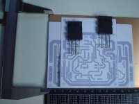
I know that it look ugly but I couldn't wait to build this one when first time I read the thread .
will wait the final release to build with a better looking .
Thank you Mr Carlos .
Thank you Mr Carlos .
Thank you Mr Carlos .
Thank you Mr Carlos .
Many people here will tell you that you are not skilled and that there are too many wires running around. 3 fans? 3 boards? Must sound like fingernails on chalkboard.
People forget that this is DIY, you make things how you yourself want to and if it works no one should complain. You spent a lot of time, it works and sounds good. I would say that this should be motivation for people to try it out themselves.
Apply for a job at DX Corp, no bias; no prejudice; honest effort is the only job requirement.
I know that it look ugly
Ugly? I don't think it looks ugly. Scary maybe but not ugly.

Yes, i do think it is scary too, but not really ugly, just some
care about wires, to join them in groups, to try to hide them.
I think he was so happy that fast made the picture,..... really friends, this amplifier call for our more deep emotions, listening some old musics, with all that clarity sent me back to the time i was young and some tears dropped from my eyes....of course i miss the young time, filled with hopes and romance... a lot of romance.
Thanks a lot Doctor Self, and the Blameless, an amplifier i have tried years ago that made me feel terrified so bad was the sonics... well, something wrong should happened those early days, now, modified, having the bootstrapp and other small things, became the best i could listen.
I am glad i have decided to try it once again.. the input is a copy from Blameless...exactly a copy, even condensers and capacitors, resistance values..everything.
I think he was so happy that made the picture and may try a better organization of wiring.
I felt scared too, the same feeling, because if a positive rail, or negative rail wire is dessolded, then rail voltage will go to the speaker, sometimes fuses does not open, and sometimes speakers burns because of that....scared was the name...really.
regards,
Carlos
I think he was so happy that made the picture and may try a better organization of wiring.
It reminds me of "during construction" crossover networks.
Yeah, those thick wires.... really...not needed.
I am using internet ADSL cable..then i remove the plastic cover... a lot of wires there, and very good, i have tested then with 25 amperes and they worked fine till 15 inches (we do not use more than that).
People loves to use those thick ones.... in excess i think, over dimensioned, overkill.
Crossover also uses this way...even length is small.
If we think about the speaker coil, the wire diameter, and having resistance, power there..we see that we overkill the stuff.
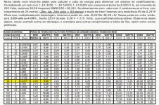
In this Brazilian power amplifier (schematic already with Jan Dupont), you see they have applied a chart at the final.... in this case, several meters of cable length, then we need some care about wire gauge.
Manual is 538K, so, if someone wants, just let me know... was sent to Jan Dupont.
I could not post because of size.
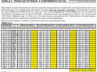
then i have produced pictures, the first one is the manual front page, the second shows power cable length in a chart, the third one shows the power losses depending cable length and gauge.
they are in portuguese, but power, lengthes, losses, all this is almost international.
regards,
Carlos
I am using internet ADSL cable..then i remove the plastic cover... a lot of wires there, and very good, i have tested then with 25 amperes and they worked fine till 15 inches (we do not use more than that).
People loves to use those thick ones.... in excess i think, over dimensioned, overkill.
Crossover also uses this way...even length is small.
If we think about the speaker coil, the wire diameter, and having resistance, power there..we see that we overkill the stuff.
In this Brazilian power amplifier (schematic already with Jan Dupont), you see they have applied a chart at the final.... in this case, several meters of cable length, then we need some care about wire gauge.
Manual is 538K, so, if someone wants, just let me know... was sent to Jan Dupont.
I could not post because of size.
then i have produced pictures, the first one is the manual front page, the second shows power cable length in a chart, the third one shows the power losses depending cable length and gauge.
they are in portuguese, but power, lengthes, losses, all this is almost international.
regards,
Carlos
Attachments
Last edited:
yes , I agree with you all about the scary wires .I felt scared too, the same feeling, because if a positive rail, or negative rail wire is dessolded, then rail voltage will go to the speaker, sometimes fuses does not open, and sometimes speakers burns because of that....scared was the name...really.
Next time will care about not only hiding wires but to find way to skip them and to be less .
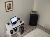
Dear Carlos. If you look at the right, up the right channel you will see a board which is the DC speaker protection , Vellemn Kit.
and that why am not afraid if something goes wrong in the amp ( I don't think ) cus you know what you share with people here .
But believe me after putting the cover back you forget the scary wires and you just , Listen and enjoy the sound coming out of 2x 8" subwoofer .
Thank you Carlos and thanks for the comments .
best wishes to all diy'rs to success on building this Amp.
good luck .
YES I WAS and Im happy .
Happy to be here as member .
Last edited:
You will see i have made that modification and the sound does not result fine.
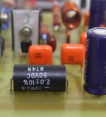
I have published picture, this condenser was increased to 820uf.
Try to read, then you will be better informed about what is going on..reading just the last post will result you gonna be lost and repeating suggestions already tested.
regards,
Carlos
A random selection of 820uF? Wow, that couldn't have worked well. Practically impossible and/or at least "very unlikely" to find a signal grade cap in that size.
Main idea: 470uF, 680uF and 820uF aren't going to work because of component variety versus bandwidth (hf failure mode action is apparent in those sizes to usually hit breakpoint during the audio band--sound awful blurry and worse), so jump the size UP to a cap that will work at a completely different bandwidth. It works like this: A much larger cap won't suddenly break into hf failure mode in the midpoint of the audio band.
Perhaps not everyone who builds DX Blame has a signal grade 220uF, thus creating a mystery why you like yours so much. Is yours Chinsan's Elite SD series or a similar signal grade from Nichicon that pre-dates ROHS?
Here's the story: 100uF is not difficult to find in signal grade; however, the difficulty of sourcing a signal grade component (works exactly as it is modeled to do), this difficulty increases along with the capacitance.
The fix: However, it is known that Nichicon commonly makes 2200uF in signal grade quality. Thus you can use it on a mixer (add at least 3 ohms resistor to ground side of only the larger cap) along with 100uF or 220uF.
Finally, the 100uF or 220uF does not enter Hf failure mode within the audio band (if and only if it is a signal grade cap), and since these are too small for the circuit, they are always in Lf failure mode; while the 2200uF is always into Hf failure mode and doesn't exhibit any crude/sudden breakpoint. With some luck and a single resistor (preferably 3 ohms or larger, with 1/2w carbon film), you can "shotgun marry" the Lf failure cap (too small) with the Hf failure cap (too large) and actually pass AC intact.
Its doable. Its not effortless and random selection is certain to fail.
Here's the selection method:
Try/test-drive 5 "most likely guesses" for model of capacitor of each given size. Keep the best.
Since the method involves 2 caps, that's 5x5, which means you'll be trying 25 times. Its not effortless at all.
The method could possibly work to find a single 470uF signal grade cap, if you happen to have a selection of different models readily available.
P.S.
There is an option to dodge the problem by using an opamp for the job. This is more likely to produce expected performance (as it can be modeled reliably) without reliance on component specific design. Just "values" can work that way. Otherwise, not so much.
I have found solution, now i have more deep bass...and without losses in treble
but will not tell... these modifications only march,28
And using the same board.
It is not the electrolitic condenser encrease.
When we go making modifications, them people perceive the circuit is mutant...they cannot assemble something today that will be entirelly different tomorrow...no modifications till march, 28
The amplifier sounds lovely... the shy bass you fix decreasing treble a little bit...for a while...in the future will not be needed, will be sonically flat....as electrically it is already flat.
regards,
Carlos
Last edited:
The German Division of DX Corp. Intl. made some big progress this weekend.
Volker's BlameES boards - nearly done.
Carlos: keep your fingers crossed.
Best regards - Rudi_Ratlos
Volker's BlameES boards - nearly done.
Carlos: keep your fingers crossed.
An externally hosted image should be here but it was not working when we last tested it.
Best regards - Rudi_Ratlos
Thank you Funky2X, i am not scared anymore.
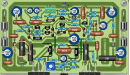
Yes, Tinitus, my boards are easy to recognize, because the one make it is the same, usually Taj....the first one was from Greg, and he created the style, others go following the good example and trying to develop a little bit.
Rudi!.... very good that, so Volker is almost ready to go.
I am very happy knowing that.
regards,
Carlos
Attachments

Heatsink for BLameES
We intend to mount the final-stage transistors (SANKENs) of the BlameES directly to the bottom-plate of the case (see attached image):
The bottom plate consists of 8mm thick Aluminium and has the following dimensions: 460 x 360 mm.
What do you think? Can a bottom-plate serve as a heatsink?
Best regards - Rudi_Ratlos
We intend to mount the final-stage transistors (SANKENs) of the BlameES directly to the bottom-plate of the case (see attached image):
An externally hosted image should be here but it was not working when we last tested it.
The bottom plate consists of 8mm thick Aluminium and has the following dimensions: 460 x 360 mm.
What do you think? Can a bottom-plate serve as a heatsink?
Best regards - Rudi_Ratlos
Bottom plate, and also the whole enclosure can be used
but are not very good heatsinks...hot air goes up, and sucks cold air from bellow the equipment...beause of that you need a big distance (long supporting feet... almost 3 inches) to reduce the air flow resistance... the bottom place have to receive several holes, at least 25 percent of the bottom plate shoud be removed with drilling machine... also, your top cover will need to have bigger roles or vents too, and to create the flow, top cover holes must be bigger in area compared to the bottom holes, to create a convection current.
This is interesting, but not efficient, works not very good, will help you but the power dissipation capacity is reduced this way, not exposed to the air, only one side will operate with 50 percent capacity of heat transference (my opinion) the other side, the other face, the one you have bellow, will transfer heat with 25 percent of the area transference.
This enormous plate, with top cover, placed over a flat table, will be good to an amplifier of 80 watts rms continuous, steady tone, non distorted watts, power heat will be almost twice (around 160 watts).... if outside the case, vertical position, exposed to free air, this same plate would be good to a 160 watt amplifier, sinking around 300 watts of heat to the air...but inside a case, as a case bottom, will be a oven, will cook all your condensers, resistances and so on....years passing everything will become dried, yellow in colour, capacitor plastic covers will crack, the yellow Silver Mica capacitors will became brown, ligth brown.
It may be good to two Dx Blame ES, playing music at average levels...it may work, maybe a fan, to exaust some air, using 8 volts as supply (not to be noisy) damped using pieces of rubber in their stand support, not to vibrate the whole case, may work fine.
I have tried this with a heathkit enclosure, all aluminium, and i have faced problems, worked in a very bad way...at the end i had to install outside heatsinks, fins in the normal vertical position to perfect cooling.
But even doing that way, we need feet to the enclosure, we need something to keep it high above the supporting surface, the table or the stand where the amplifier will rest... also distance from the wall is needed, at least 4 inches distant from the back wall, at least 4 inches to the furniture cover, door opened or not having doors if installed inside a furniture.
My experience with such things were obtained in a day by day basis, and of course, 29 degrées average environment,...if your place is 10 degrees average, then everything changes, and dissipation will be better...we do not want surface to reach 56 degrees celsius, this is the target after hours full undistorted continuous power... doing this way, your equipment will survive you.
Heat must go out, or be transfered to the air... this natural air flow movement is what makes wind.
regards,
Carlos
Attachments
Last edited:
- Status
- This old topic is closed. If you want to reopen this topic, contact a moderator using the "Report Post" button.
- Home
- Amplifiers
- Solid State
- Dx Blame ES .... based into the Blameless, i am trying a new amplifier