A link for you to listen the Dx Blame ES
recording using Panasonic electret condenser microphone cartridge...the acoustic conditions were not good, a normal room, a bedroom, a computer and not carpet or absortion material, only a small curtain...the room ressonance is 400 hertz....my home ressonance (entire home, door opened) is 240 hertz
YouTube - Dx Blame ES, Christmas day test II
regards,
Carlos
heatsink for the second VAS transistor, the BD139 is a very small and thin
piece of aluminium, around 2 thirds of an inch side.
Heat is small there, this is for stability, thermal stability, to avoid transistor to change parameters...current there is not so big, so power there is very small.
VAS current is around 5 miliamps and rms voltage, audio swing, from colector to emitter is around 20 volts (RMS)
regards,
Carlos
Yes, i know it is in wrong place and will be there till i found another way to face
2.2uf capacitive loads.
The amplifier was better into the scope this way..read the entire thread, this was mentioned earlier.
Done intentionally, on purpose, so, was pre meditated, planned this way, created this way, measured this way, consciously drawn in the wrong place, outside standards, against rules.
Receive a hug my dear.
regards,
Carlos
Last edited:
15uH will show 1 ohm at 10khz and 2 ohm at 20khz. This may result in rolled-off highs with low inductance high end tweeters, not to mention low impedance ribbons...
If this amplifier can't drive a capacitive load with 10 times less inductance, there is probably some mistake in design")
The RC load should be at the other side of the inductor. Stability should be much better that way. The output stage really needs a low ohmic load above 1Mhz for proper phase margin and gain control.
If this amplifier can't drive a capacitive load with 10 times less inductance, there is probably some mistake in design
The RC load should be at the other side of the inductor. Stability should be much better that way. The output stage really needs a low ohmic load above 1Mhz for proper phase margin and gain control.
Yes, i do think the same as you Eva, but i do not know how to fix
I will love to reduce this enormous output inductor, i just do not know how to do it...i have enormous over shot without it, reason why it is there.
Can you help?
It is wrong, i know that, but this is the only way i had, my technicall resources are limited, i use hard work, try and error basis to overcome my limits.
It is sounding lovely, i would say unbeatable this way.... and this confirms to me what i had as suspections my whole life, the correct thing into scope and simulators does not correspond, does not match real live performance with the amplifier playing..the blameless, build the way it was, say, the original schematic, reproduce a very thin sound, nothing special.
I see it has an error, but i do not know where is the error...i want to fix, but i do not know how.
It was keept this way because sounding lovely, wonderfull!, unbeatable... smashed all i have in my home, including the digital one...but for sure i would love it facing capacitive loads and not using big inductors in the output line.
I would offer you a good glass filled with lovely hot Colacau (excelent soluble Spanish Chocolate) for that job!
Help!
Carlos
Last edited:
If people want to really help me to fix that, or to reduce the output coil without
to have the overshot i will be very gratefull.
Of course i need help to fix, not suggestions about what to try, i have tried almost all possibilities into simulator and real life tweakings, so, the cause must be detected in advance.
I have the Multisim 10 files if someone really wants to help..to point errors there are thousands folks can do it, i want someone that able to offer the solution... having really good will to help, in a friendly and positive way.
regards,
Carlos
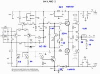
The 10nF capacitor impairs the current mirror above 200khz, it should not be there, it does not improve stability.
The 100 ohm pot is not the way to trim DC offset. There should not be any substantial DC offset in this amplifier without any trimming.
The 33R bypassed by 22nF on driver bases are calling for trouble, you usually want resistive input impedance at high frequencies and low impedance at low frequencies (R and L in parallel).
The 100uF in parallel with the Vbe multiplier is calling for local instability, a capacitor should not be placed there without series resistance, the output impedance of a Vbe multiplier is actually quite low due to the high local feedback.
You may find that diodes work better than the 100R and 200R on the rails.
2.2uF between the emitters of the drivers is also calling for local instability. Sometimes things don't work as expected (when you are only interested in the simple answers to complex questions).
The output stage usually needs 2 to 10 ohm of resistive load above 500Khz-1Mhz, that's the purpose of the RC at the output.
I think the the 27pf capacitor from the base of the BC546 to GND is not doing anything useful.
The 100R to 2.2R ratio of the BC546/BD139 emitter resistors is also calling for trouble (45). Emitter degeneration is used to force a lower current gain and get low phase shift up to a higher frequency in return. Theoretically a 100Mhz Ft transistor with a forced gain of 50 will roll off at 2Mhz, this is too low. Forced gains are usually 10 or less to get higher bandwidth.
Have you ever tried frequency compensation with two poles and a zero rather than a dominant pole?
Carlos,
if not done it is a good idea to ground the heat sink in a way to prevent oscillation when things are not in a metal case with common ground point.
But in your case I would ground the heat sink through a low value resistor say 10 Ohm as such it will be lossy to parasitic capacitances and inductances, some times a straight wire can also be bad.
Cheers Michael
Last edited:
100 respectable kisses for you dear Eva
You fixed!
Soon i will provide fixed schematics...no more overshot, pure square wave, full power till 20 Khz.
distortion is even lower now.
Almost all your suggestions were used, not all, but the ones fixed.
The output inductor is now 1 microhenry.
You are very good Eva.
My deep respects and congratulations.
regards,
Carlos
Attachments

Zobel returned to the correct point, extra 27pf capacitor removed
10N capacitor removed, 22n from the phase advance system (Sansui) removed and now playing stable....but really, the phase advance has a lovely "touch" into the treble...a pitty to remove this one...well... was needed...was one from the unstabilizing factors.
regards,
Carlos
10N capacitor removed, 22n from the phase advance system (Sansui) removed and now playing stable....but really, the phase advance has a lovely "touch" into the treble...a pitty to remove this one...well... was needed...was one from the unstabilizing factors.
regards,
Carlos
Attachments
You see, really looks alike Doctor Self Blameless...of course
This one was based on it... assembled and tweaked for sonics.
Now you have double guarantee, the "inspiration" and the Corporation guarantee.
Also Eva revision.
With that crew.... it is easy to produce lovely things.
This is the best wide world amplifier!
You do not believe?.... good!, assemble and them come here and tell me what you perceived...previously write the list of amplifier this one have eated during the breakfast.
Sorry competition, you loose!.... wanna an advice?, do not tell folks but copy this schematic to be produced in your line.... also be more humble.... Doctor Self did that!..i have only tweaked for sonics.
Now accepting 2.2uf, the square wave is not perfect this way, but very good.
regards,
Carlos
Attachments
Last edited:
I ensure you, and i can say that because i am watching and monitoring what is going
on here.
the amplifier is more stable when the zobel is installed with the speaker, or, in the wrong technicall and traditional position.
My board is a mess..well.... was made this way to unstabilize, and it does very well such kind of things.
Measuring dc directly over the emitter resistances, the output section, and i felt it oscilated because the readings increased a lot..fast i removed the probe point and switched the amplifier off.... then i have repeated and once again...then i moved the zobel filter to the output and this finished...in my personall unit the zobel will at the output position.
I do love this amplifier, but really folks, i have not courage to suggest you to build because i can see it may be problematic depending the board, speaker or installation.
I will be selfish and will not tell you do build...will be only mine..ahahahahah!
But, other friends will use, soon we gonna have boards made by Taj, also an Orkut friend is producing boards, well, these boards will be tested and we gonna see what happens further.
Maybe my hand was touching the BD139 (VAS) colector while adjusting...i have a heatsink, and this can pick things too...do not know.... you know, touching both same time, the output line and the BD139 colector may have created that trouble.
Sounds lovely...but it is only mine!
Attachments
Last edited:
Dear Carlos,
you know:
I am one of your most loyal fans concerning audiophile-sounding AMPs and since I built your DXAMP I will not try anything else that does not originate from the DX Corporation.
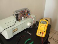
The DXAMP (in its wooden enclosure on the right side of the workbench) is already sounding so mature, smooth, full of emotion, crisp, direct ...
The most beautiful bass fundament I ever heart!
It can absolutely compete with any other AMP I ever listened to!
It is playing: ... divine .
.
I made a lot of mistakes concerning the mechanical construction of your DXAMP resulting in a lot of wires going back and forth and lots of little
PCBs mounted eyerywhere in the case (your DXAMP was my first DIY - piece: but a real success) - so I wanted to optimize it, ..., make it "professional" .
I followed your thread concerning the DX Blame ES, read about it burning down, read about EVA's intervention and your breakthrough!
Go on with the Blame ES, the most beautiful AMP of the world!
I will build this one, for sure, ... I already ordered parts (SANKEN) for it ... and ... big wish of mine: I would join the DX Corporation:
CARLOS: Technical director
EVA: Technical assistant and revisor
TAJ: Art director
...
RUDI: BOM director
Best regards and have a nice Christmas - Rudi_Ratlos
you know:
I am one of your most loyal fans concerning audiophile-sounding AMPs and since I built your DXAMP I will not try anything else that does not originate from the DX Corporation.
An externally hosted image should be here but it was not working when we last tested it.
The DXAMP (in its wooden enclosure on the right side of the workbench) is already sounding so mature, smooth, full of emotion, crisp, direct ...
The most beautiful bass fundament I ever heart!
It can absolutely compete with any other AMP I ever listened to!
It is playing: ... divine
.I made a lot of mistakes concerning the mechanical construction of your DXAMP resulting in a lot of wires going back and forth and lots of little
PCBs mounted eyerywhere in the case (your DXAMP was my first DIY - piece: but a real success) - so I wanted to optimize it, ..., make it "professional"
.I followed your thread concerning the DX Blame ES, read about it burning down, read about EVA's intervention and your breakthrough!
Go on with the Blame ES, the most beautiful AMP of the world!
I will build this one, for sure, ... I already ordered parts (SANKEN) for it ... and ... big wish of mine: I would join the DX Corporation:
CARLOS: Technical director
EVA: Technical assistant and revisor
TAJ: Art director
...
RUDI: BOM director
Best regards and have a nice Christmas - Rudi_Ratlos
Last edited:
- Status
- This old topic is closed. If you want to reopen this topic, contact a moderator using the "Report Post" button.
- Home
- Amplifiers
- Solid State
- Dx Blame ES .... based into the Blameless, i am trying a new amplifier