Hi everybody,
I thought I would start a new thread regarding a perhaps new(?) idea how to load the LTP stage.
As we know there are people who prefers a CCS circuit at the tail of the LTP while others would choose a simple resistor, both have their pros and cons objectively/subjectively.
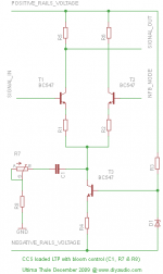
Having thought about it I came up for some time ago with an idea where we might perhaps enjoy the best of both, so I came up with the following circuit attached as a picture.
With the circuit as shown in the attachment we can enjoy both high PSRR and still get the 'quality' of a resistor as a current source on the LTPs tail.
I didn't have much more to say and just wanted to present the idea for the rest of you, so if you have any comments then let us know.
Cheers Michael
I thought I would start a new thread regarding a perhaps new(?) idea how to load the LTP stage.
As we know there are people who prefers a CCS circuit at the tail of the LTP while others would choose a simple resistor, both have their pros and cons objectively/subjectively.
Having thought about it I came up for some time ago with an idea where we might perhaps enjoy the best of both, so I came up with the following circuit attached as a picture.
With the circuit as shown in the attachment we can enjoy both high PSRR and still get the 'quality' of a resistor as a current source on the LTPs tail.
I didn't have much more to say and just wanted to present the idea for the rest of you, so if you have any comments then let us know.
Cheers Michael
Attachments
Last edited:
That will give some local feedback, lowering the gain. It will make the transistors better matched by local feeback.
I dont think so. The gain of an LTP is not dependent on the tail resistance.The voltage at the R1 R2 C1 CCs junction should stay constant so it provides no feedback.
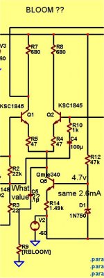
BLOOM ??  I just had to try it . In[Pix 1] ,I used a basic bootstrapped amp with a standard tail and a CCS biased with a Zener.
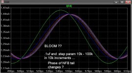
In [pix 2] , the phase of the NFB side of the LTP changes as LT .step 'ed from 10k-100k. I am not sure what this does to the real sound or whether the RC (.1u/ 10k - 100k) is even within the ballpark.
Both the FFT , OLG and total gain of the amp stayed pretty constant no matter how I stepped {RBLOOM} ...the trimmer. The global feedback of the amp "swamped out" any effect of the phase shift at the input stage.
If you could be more specific with ballpark component values , I will try them .
OS
I just had to try it . In[Pix 1] ,I used a basic bootstrapped amp with a standard tail and a CCS biased with a Zener.In [pix 2] , the phase of the NFB side of the LTP changes as LT .step 'ed from 10k-100k. I am not sure what this does to the real sound or whether the RC (.1u/ 10k - 100k) is even within the ballpark.
Both the FFT , OLG and total gain of the amp stayed pretty constant no matter how I stepped {RBLOOM} ...the trimmer. The global feedback of the amp "swamped out" any effect of the phase shift at the input stage.
If you could be more specific with ballpark component values , I will try them .
OS
Attachments
OS,
the capacitor should be relatively large and be able pass by the whole audio band except DC, the variable resistor will look like a R loaded LTP, but... as the capacitor C1 blocks DC the CCS is added to provide the LTP with a current bias.
I guess you could look at the FFT with different R settings and see how the different harmonics changes in value, eg. the sonic 'bloom'.
btw, the 'bloom control' variable R could be of high value, let say 1 MOhm, so when set to max R value it will have minimal effect on the LTP and the circuit will look more like a CCS loaded LTP, trim the R to minimal R value and the LTP will look like a R loaded LTP, let say maybe down to 1 k Ohm.
LO,
I am not advocating for CCS or R loaded LPTs in this thread, but some are of distinct opinions about which one serves the LTP best in terms of sonic quality, then there are some technical aspects too, some may say a R loaded LPT doesn't have so good PSRR etc...
Cheers Michael
Last edited:
- Status
- This old topic is closed. If you want to reopen this topic, contact a moderator using the "Report Post" button.