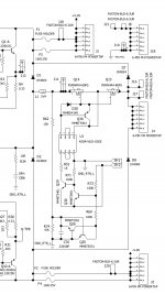
A PNP emitter follower probably works better than a resistor would in quickly discharging the gates of the MOSFETs. It might be non-desirable that R7 can bleed off the precious pv voltage. I have a MOFET relay built into my latest amp project. I got the MOSFET and the pv driver from avnet. I bench-tested the relay and it worked very well. The circuit is posted below if it helps. Q36 is the emitter follower:
Attachments
Hi,
Just in case you want to try it attached it is schematic of my solid state relay using an avago Dual Channel Photovoltaic MOSFET Driver. I have been using it in my LM3886 amplifier for about one year with no problems. You can see the scope open/close time signal in my thread Protecting the speaker output using a microprocessor
Just in case you want to try it attached it is schematic of my solid state relay using an avago Dual Channel Photovoltaic MOSFET Driver. I have been using it in my LM3886 amplifier for about one year with no problems. You can see the scope open/close time signal in my thread Protecting the speaker output using a microprocessor
Attachments
Substituting a 2N5401/1N4148 per nattawa's diagram gave a longer turn-off time than the resistor in LTSpice. I got 65uS.
Using tauro0221's circuit, which looks a lot like one on Rod Elliott's site, required that I add another HCNR200 to the stack before it started to work. But once it did work in LTSpice, I got about a 5uS turn-off time. Not bad.
I'm not sure I understand these results. Maybe it has something to do with base/gate capacitance of the added PNP/NJFET.
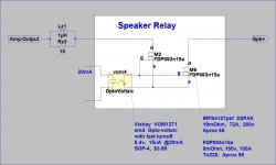
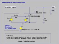
The relatively new Vishay VOM1271 opto-photovoltaic device seems to be the best device to use for driving a pair of mosfet relay switches. It includes a fast turn off circuit. The opto LED needs to be driven between 10mA and 20mA for best results.
See attachment for the mosfet relay concept, and the vom1271 datasheet at http://www.vishay.com/docs/83469/vom1271t.pdf
Note that I haven't tried this circuit yet, though I have bought the bits.
Paul Bysouth
See attachment for the mosfet relay concept, and the vom1271 datasheet at http://www.vishay.com/docs/83469/vom1271t.pdf
Note that I haven't tried this circuit yet, though I have bought the bits.
Paul Bysouth
Attachments
Paul, those switching times shown in the VOM1271 datasheet look good. But do I understand the waveform for the switching time test correctly? It appears that the output is inverted relative to the input. Is it an inverting device?
Vishay does not provide a Spice model that I can find. Too bad.
Vishay does not provide a Spice model that I can find. Too bad.
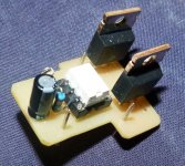
I am Quite happy with the "old fashioned" PVI1050A .
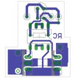
Working great as a Songle 30A relay drop-in I made a while ago for my 5 channel HT amp with 5 LJM's L15D's .
very low RDsOn fast switch on an off , can't find scope pictures at the moment , but will keep looking .
Cheers ,
Rens
I know , some pins of the PV are not seated , but my rottie pinched my glasses from the bench before I took the picture of the PCB
Attachments
Last edited:
post87,
no resistor from gate to source?
My compliments on reading the schematics AndrewT
Cheers ,
Rens
The relatively new Vishay VOM1271 opto-photovoltaic device seems to be the best device to use for driving a pair of mosfet relay switches. It includes a fast turn off circuit. The opto LED needs to be driven between 10mA and 20mA for best results.
See attachment for the mosfet relay concept, and the vom1271 datasheet at http://www.vishay.com/docs/83469/vom1271t.pdf
Note that I haven't tried this circuit yet, though I have bought the bits.
Paul Bysouth
Hi Paul ,
Just interested if your relay works
")
Cheers ,
Rens
Rens,
No I haven't built the mosfet relay yet! I've spent most of the year working on a 1000 watt class D subwoofer, so no time for my projects.
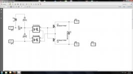
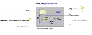
If anybody wants to use LTspice to simulate the vom1271 optovoltaic, I use either of the two following `simple' models below.
Some time ago (3 years ago I think), I built a number of prototype 250 watt power amps that used `mosfet relays' in the power rails. These used large FQA32n20c mosfets driven by a rather complex opto coupler based drive circuit, and where situated after the power supply Capacitors and fuse, and before 2*47uF caps on the power amp. If either fuse opened, then both `relays' opened and disconnected both power rails. Experiments with pulling a fuse out while the amp was working (a bit scary when you have +-70v rails) did not produce any audible thumps - the test signal just stopped!
Regards,
Paul Bysouth
No I haven't built the mosfet relay yet! I've spent most of the year working on a 1000 watt class D subwoofer, so no time for my projects.
If anybody wants to use LTspice to simulate the vom1271 optovoltaic, I use either of the two following `simple' models below.
Some time ago (3 years ago I think), I built a number of prototype 250 watt power amps that used `mosfet relays' in the power rails. These used large FQA32n20c mosfets driven by a rather complex opto coupler based drive circuit, and where situated after the power supply Capacitors and fuse, and before 2*47uF caps on the power amp. If either fuse opened, then both `relays' opened and disconnected both power rails. Experiments with pulling a fuse out while the amp was working (a bit scary when you have +-70v rails) did not produce any audible thumps - the test signal just stopped!
Regards,
Paul Bysouth
Attachments
As I'm still working on the amplifier, there is no problem to put or not put fuses...
Your mosfets looks Nice, however 120V is not enough to me. And 4127 has quite low on resistance, with small package, and moderate price.
My second possibility to use triac crowbar instead of relay.
Sajti
Your mosfets looks Nice, however 120V is not enough to me. And 4127 has quite low on resistance, with small package, and moderate price.
My second possibility to use triac crowbar instead of relay.
Sajti
- Status
- This old topic is closed. If you want to reopen this topic, contact a moderator using the "Report Post" button.
- Home
- Amplifiers
- Solid State
- MosFet Relays