Hi Guys
I've used back-to-back mosfet switches for all kinds of things including inrush current limiters. I've used the PVIs which are good for slow on/off; I've used voltage-divider drive so the control circuit has a similar supply range as the signal being controlled; and I've used floating supplies with interfaces as required to grounded circuitry.
The bilateral switch can easily be modified to have current clamping and limiting options, but as a switch they work best with fast gate drive. There are a lot of gate drive ICs now with currents up to 9A for super-fast on/off.
The key to the drive problem is to use a floating supply. This is just a 12V circuit that does not have to provide much in the way of current. A small aux transformer will do. The transition currents required to charge/discharge the gates come from small ceramic bypass caps across the driver chip supply pins.
Interfacing from the audio muting circuitry or other controls to the floating gate drive can be via optocoupler or PVI. The only issue with either of these is their coupling times. faster optos are coming out every day.
The main drawback with the mosfet bilateral switch is its capacitance from end-to-end when the voltage across it is low. C rises under this condition and there is a graph showing this for integrated mosfet relays. This C is more problematic with high-impedance circuits.
Even low miliohm circuits can effect output damping and THD from some amps.
At high currents some heat sinking is advised, as with using mosfets of higher on-resistance and/or too-low gate drive.
Have fun
Hi Struth,
glad to read that there is at least one person who also sees the need of a proper gate drive.
Your setup is the obviously straight forward approach, which allows proper switching.
But it needs:
1. AC-Signal to fed the floating supply
2. Transformer for the floating supply
3. Rectifier for the floating supply
4. Optocoupler
5. Gate driver
That's even more RollsRoyce than my proposal...
Fortunately we do not switch our speaker repetitive with multiple hundrets of kHz... It is more about single events. Means as soon as we reach switching times below 1us most large MosFets allow to use the full current-voltage-window.
There is no need to offer 9A gate drive current peaks.
The solution of my early postings is already more than sufficient.
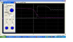
The attached screen shot is showing the turn OFF characteristic when switching a mostly resistive/inductive load of 115V / 45A.
You can see that the gate plateau and voltage transition of the load is in the range of 400ns. Due to the inductance of the heavy resistors we get an overshoot which is perfectly clamped by the varistor and then rings off in a well behaved manner.
Time scale is zoomed by factor 10, means 2us/grid
White trace is the voltage across the switch measured with a differential probe 1:100 means 50V/grid.
Red trace is the gate drive voltage with 1:10 probe means 5V/grid
glad to read that there is at least one person who also sees the need of a proper gate drive.
Your setup is the obviously straight forward approach, which allows proper switching.
But it needs:
1. AC-Signal to fed the floating supply
2. Transformer for the floating supply
3. Rectifier for the floating supply
4. Optocoupler
5. Gate driver
That's even more RollsRoyce than my proposal...
Fortunately we do not switch our speaker repetitive with multiple hundrets of kHz... It is more about single events. Means as soon as we reach switching times below 1us most large MosFets allow to use the full current-voltage-window.
There is no need to offer 9A gate drive current peaks.
The solution of my early postings is already more than sufficient.
The attached screen shot is showing the turn OFF characteristic when switching a mostly resistive/inductive load of 115V / 45A.
You can see that the gate plateau and voltage transition of the load is in the range of 400ns. Due to the inductance of the heavy resistors we get an overshoot which is perfectly clamped by the varistor and then rings off in a well behaved manner.
Time scale is zoomed by factor 10, means 2us/grid
White trace is the voltage across the switch measured with a differential probe 1:100 means 50V/grid.
Red trace is the gate drive voltage with 1:10 probe means 5V/grid
Attachments
Member
Joined 2009
Paid Member
I've only tried this approach once:
http://www.diyaudio.com/forums/soli...imple-symmetric-amplifier-13.html#post2939602
It works as intended but no doubt can be further optimized.
http://www.diyaudio.com/forums/soli...imple-symmetric-amplifier-13.html#post2939602
It works as intended but no doubt can be further optimized.
On one hand I am promoting a proper gate drive and taking care of the MosFet SOA...
On the other hand there is no doubt, that the ultra simple drive from a photovoltaic coupler will work in terms of average audio reliability requirements.
Many companies and customers are not interested at all in having products, that can handle all kinds of unpleasant events.
It makes the product more expensive and many people feel bored anyway when the rate of gadget renewal is to low. From this point of view a proper gate drive for the MosFet relay in an audio amp is a clear overdesign.
The simple approach will fail only in seldom situations.
Just in case someone is interested, I used the concept of back-2-back MOSFETs in a SS relay with a floating switch and ground-referenced control input. This is based on an isolated 5VDC>+/-12VDC converter from Traco, and an opto-isolated MOSFET driver.
Rds(on) is less than 6mohms but gets moot as the wiring contributes more than that, normally.
See schematic and PCB attached.
With a gate resistor of 47 ohms the switching time is around 80nS, with 330 ohms it's about 300nS.
jan didden
Sorry to repeat myself...
")
jan
Attachments
Hi Guys
A mosfet floating switch with floating supply for gate drive need no more coupling to grounded circuitry than a photocoupler for on/off. No audio signals. Nothing fancy at all.
As far as a straight on/off switch goes, the gate drive can be nonfancy but it must be significant inasmuch as a hard 'on' hard 'off' gate signal is needed. Otherwise the channels are not at their lowest on resistance.
It would be interesting to see what THD contribution this would present. Fuses and relays in amplifier outputs have been measured, and relays in particular can be problematic in other ways. I had relays cause such bad distortion that I thought the amp was malfunctioning.
A PVI on its own won't turn the mosfets on hard enough to realise lowest Rds-on. I know this from using them. The PVI can certainly be used in place of a photocoupler but it is more expensive, so why? unless you already have them - a 4N25 is like 25-cents, where a PVI5080 is a couple of dollars. I like PVIs and have used them in their linear mode as well as for switching.
Have fun
Kevin O'Connor
londonpower.com
Hi Guys
The earlier comment by Jean-Paul regarding under-rated relays being used is quite to the point.
A speaker is nominally a high-current load, so demands the use of a relay contact rated for high AC current. Many relays have "TV" ratings that reflect their use in television circuits. The turn-on surge currents are quite high, but typically a fixed ratio compared to the continuous current. TV3 to TV5 ratings indicate how rugged the contact is and how well it resists arcing when switching hot loads.
In previous builds, I always used output relays with these kinds of ratings. Fortunately modern relays are quite small and respond within about 2-5ms.
The relay should be wired normally-open so that the default at initial power-on is to disconnect the speaker from the amp. If output DC/RF is okay, then the relay can switch on and make the connection. Ideally, at the input of the PA there is also a mute circuit that opens just a little bit after the relay is closed so that the relay does not have to switch hot. The input mute should also be activated for a fault or at turn-off.
Have fun
Kevin O'Connor
londonpower.com
A mosfet floating switch with floating supply for gate drive need no more coupling to grounded circuitry than a photocoupler for on/off. No audio signals. Nothing fancy at all.
As far as a straight on/off switch goes, the gate drive can be nonfancy but it must be significant inasmuch as a hard 'on' hard 'off' gate signal is needed. Otherwise the channels are not at their lowest on resistance.
It would be interesting to see what THD contribution this would present. Fuses and relays in amplifier outputs have been measured, and relays in particular can be problematic in other ways. I had relays cause such bad distortion that I thought the amp was malfunctioning.
Feel free to read the first page of the thread.
Sorry to repeat myself...
jan
Sorry that I did not comment earlier.
No doubt, that's also a proper implementation. The relation of component count and performance is pretty nice.
It's more a question of personal taste that I am not in love with flyback converters close to audio signals. But that's silly, I know. Every tone that I intend to feed into my amp these days has already gone through kilometers of wires next to flybacks in modern audio processing and distribution systems....
Hi Guys
The first page of the thread has no THD info about mosfet relays. A listening test does not prove such a circuit is better than a relay or fuse. When the latter are working as expected, you cannot tell they are there, however, Self, Cordell and others have measured the THD of relays and fuses, so we have a quantified notion of what they do to the signal.
Have fun
Kevin O'Connor
londonpower.com
Sorry that I did not comment earlier.
No doubt, that's also a proper implementation. The relation of component count and performance is pretty nice.
It's more a question of personal taste that I am not in love with flyback converters close to audio signals. But that's silly, I know. Every tone that I intend to feed into my amp these days has already gone through kilometers of wires next to flybacks in modern audio processing and distribution systems....
Not silly at all, I believe that is a valid consideration.
It's just that I don't believe it has an impact in this implementation.
In the extreme you can even get excited about the ripple on the power supply of a closed mechanical relay.
In theory, that can modulate the ontact pressure and thus modulate the contact resistance.
How far you want to go.
jan
Hi Guys
The first page of the thread has no THD info about mosfet relays.
londonpower.com
Well in posting 3 and 4 I tried to measure and had to accept that the distortions are far below any of my measurement capabilities.
In posting 3 I measured the THD at the output of amp with reasonably low distortion and found no difference with and without MosFet relay.
In post 4 I described that I measured the signal across the MosFet relay itself and found that there the distortion of the voltage drop across the MosFet is still unmeasurable for me, due to the noise when measuring small signals in the range of few mV, which limits this measurement to -60db.
The series resistance of the switch is approx factor 1000 less than the speaker resistance. At the same time the nonlinearity of this small series resistance is below -60db. Means the MosFet relay acts as a very constant series resistance with a variance of less than -60db.
Assume we have 8 Ohms speaker and put in a series resistor of 8 mOhm:
When the amp delivers 10V we will find 9,99000999V at the speaker.
Now let's calculate how the signal will be affected by the change of RdsON, which is less then -60dB of 8mOhms.
...means the RdsON could vary up to 8,008mOhms:
When the amp delivers 10V, now we will find 9,99000001V at the speaker.
Consequently the non linearity of the switch will distort the output signal about 0,0000098V.
Related to the speaker signal of 9.99V signal this variance of less 9.8uV translates to distortion levels below -120db.
As soon as my class D amps become better than THD<0.0001% I have to check the relay more detailed.
How far you want to go.
That's the key question.
And I am convinced I would not hear the difference between your switch with a flyback and the same with a battery.
But I would feel more audiophile with a battery. That's the silly point.
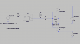
I want to build a simple MosFet relay for switching the speaker output from an amp with +-50 V rails using locally available parts. This is what I came up with.
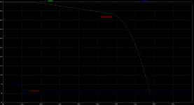
LTSpice says the turn-off time from 50V to 0V is less than 100us.
Does this look like a reasonable design?
LTSpice says the turn-off time from 50V to 0V is less than 100us.
Does this look like a reasonable design?
Attachments
NB at 65V peak out into 8 Ohms, the distortion is about -150 dB down. Even across the actual mosfets switches, the distortion is in the ppm range. Bottom line, SSLR distortion is negligible for all practical purposes.
Exactly my experience. The distortion I measure on the amp output is the same as what I measure across the switch, indicating that the switch impedance is nicely resistive and linear.
jan
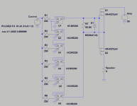
I had intended to use a separate transformer and dc supply for the floating 9V, but I like Bonsai's approach using PV diodes instead of an external power source much better. I was unable to find a Spice model for the TLP191 that Bonsai uses, so I stacked some HCNR200's (which has an available Spice model) to attempt a similar emulation in LTSpice. Here's what I got. I trimmed R7 for the best turn-off time (at the expense of turn-on time, which is unimportant to me as long as we stay within the SOA of Q1 and Q2). I got a turn-off time of around 40uS. Bonsai, you say your circuit has a turn-off time of less than 250 uS. Have you tried using an external resistor to tweak the turn-off time of your circuit?
Attachments
Last edited:
- Status
- This old topic is closed. If you want to reopen this topic, contact a moderator using the "Report Post" button.
- Home
- Amplifiers
- Solid State
- MosFet Relays