I settled a simple rectifier + RC-Filter in order to get a proper DC source( Rectifier, 10 000uF, 5 Ohms, 100 000uF, 2.2 Ohms).
This allows to measure up to 7A.
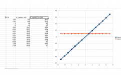
In order to allow best comparison of both current directions, I always measured both directions directly by swaping switch connection, but keeping the DC source and both DMM untouched.
The only imperfection which I found was a slight increase of the switch resistance towards higher currents, seems like 0.2 mOhm increase due to slight temperature increase at 7A.
This allows to measure up to 7A.
In order to allow best comparison of both current directions, I always measured both directions directly by swaping switch connection, but keeping the DC source and both DMM untouched.
The only imperfection which I found was a slight increase of the switch resistance towards higher currents, seems like 0.2 mOhm increase due to slight temperature increase at 7A.
Attachments
Just in case someone is interested, I used the concept of back-2-back MOSFETs in a SS relay with a floating switch and ground-referenced control input. This is based on an isolated 5VDC>+/-12VDC converter from Traco, and an opto-isolated MOSFET driver.
Rds(on) is less than 6mohms but gets moot as the wiring contributes more than that, normally. One good thing about the floating driver is that Vgs remains constant during the signal cycle so Rds(on) also remains constant, essentially a linear resistance. This is different in most MOSFET switches where Ron varies considerable during the signal cycle giving rise to distortion.
See schematic and PCB attached.
Works very well, of course, except that when switching a source that cannot sink current like a power supply, there's quite some switch-off ringing, and layout and local decoupling become very important. This is not important for a speaker relay but I build this for a measurement purpose so for me this IS important. With a gate resistor of 47 ohms the switching time is around 80nS, with 330 ohms it's about 300nS.
jan didden
Attachments
Last edited:
I prefer my versionJust in case someone is interested, I used the concept of back-2-back MOSFETs in a SS relay with a floating switch and ground-referenced control input. This is based on an isolated 5VDC>+/-12VDC converter from Traco,
 :
:Completely static, with an eternal battery.
DC-DC modules are nasty little things, spreading HF switching residues magnetically or across the common-mode barrier.
hi jan
there is a very good article by rg keen A dc fault protection circuit for audio amplifiers.
This uses IR pv1050n (available from farnell ) photo voltaic mos-fet drivers which provide
isolation between speaker output or psu rails and the driver circuit this is very similar
to your circuit with a different driver SI once made a bls 100 a common source bidirectional switch as a relay replacement for telecom use
richie
Just in case someone is interested, I used the concept of back-2-back MOSFETs in a SS relay with a floating switch and ground-referenced control input. This is based on an isolated 5VDC>+/-12VDC converter from Traco, and an opto-isolated MOSFET driver.
Rds(on) is less than 6mohms but gets moot as the wiring contributes more than that, normally. One good thing about the floating driver is that Vgs remains constant during the signal cycle so Rds(on) also remains constant, essentially a linear resistance. This is different in most MOSFET switches where Ron varies considerable during the signal cycle giving rise to distortion.
See schematic and PCB attached.
Works very well, of course, except that when switching a source that cannot sink current like a power supply, there's quite some switch-off ringing, and layout and local decoupling become very important. This is not important for a speaker relay but I build this for a measurement purpose so for me this IS important. With a gate resistor of 47 ohms the switching time is around 80nS, with 330 ohms it's about 300nS.
jan didden
I think if you use a low enough Rds(on) mosfet, and you turn it on hard, the channel Rds(on) modulation can be quite small - 1ppm distortion (the limit of AP) has been measured by a member of this forum. In my SSR article, I show a plot of Rds(on) variation from the device data sheet, and its almost flat up until about 40 A (yes, 40 A). SSR is with out a doubt the correct way to go for speaker muting and protection.
You're gonna have to crowbar its gate in order to get rid of its gate charge quick enoughI think if you use a low enough Rds(on) mosfet, and you turn it on hard...
At 1 ms the device SOA capability is 7 A at 65 V. If you switch the device at 100 us the SOA capability is 70A.
Using photo diode to drive th gates does result in slower switching. I used 2 in parallel on the e-Amp control board. However, if you switch the speaker ground return line, you can direct drive the gates, and then turn on turn off times are less than 30 us.
Using photo diode to drive th gates does result in slower switching. I used 2 in parallel on the e-Amp control board. However, if you switch the speaker ground return line, you can direct drive the gates, and then turn on turn off times are less than 30 us.
It is great to see, that more and more enthusiasts start to trust in the Back2Back arrangement of two MosFets for speaker relay applications and measurement applications as well.
Also thanks to David and Jan for getting the spelling of the title corrected.
It is the way like Jan guessed, in Germany we write 'Relais' and my ignorant brain simply mixed the languages
Stay tuned, more errors to come:
Also thanks to David and Jan for getting the spelling of the title corrected.
It is the way like Jan guessed, in Germany we write 'Relais' and my ignorant brain simply mixed the languages
Stay tuned, more errors to come
:Well Chocoholic your'e not alone in the desert.I'm busy with these things already for some time now and it works very well.But I think your control circuitry is too complex.
It can be done with a single photovoltaic coupler as already mentioned by DAI.
He mentions the old International Rectifier part PV1050N, but Toshiba has a few of them an newly also Panasonic Electric works :APV1121S cost arount 1.50 Euro at Mouser.These are simply optocouplers that DELIVER a voltage at the output.
Some people's reactions in this tread are about the off-switching time,but this is really a non-issue compared to the off switching time of a electro-mechanical relay.
And not to mention the danger of the contacts welding together.
Analog:
If the relay is high quality and in good condition, then I cannot measure and cannot hear any issue with a relay. Relays are fine, except old/defect/poor quality.
When I took one relay from my shelf I found an ugly high order spectrum with peaks in the range around -80db. Knocking a few times to its plastic cover 'repaired' it...
The above experiences are my motivation to move away from the relays.
Hi I experience a lot of defective relays in audio equipment especially in japanese quality amps. For some reason Sony engineers (amongst others) design their amps for years now with the same crappy quality relays with gold contacts for speaker switching. The used relays often can not switch more than 2 A which is a design error on itself. These relays burn in easily as gold is soft and then they fail eventually starting with channels fading or crackling. We know that current switching should be done with (hard) silver (or silver/nickel 90/10) contacts. Voltage switching i.e. input switching in amps should be done with gold contact signal relays. This of course counts for audio applications, for industrial use there are other materials. This gold/voltage and silver/current issue is common knowledge which is documented at relay manufacturers. So why Sony/Kenwood etc. guys still make the same mistake I don't understand....
I found that using simple pin compatible replacement industrial relays from Schrack that have high current switching capacity and silver/nickel 90/10 contacts is the most easy and convenient solution to repair such amps. They also use less current which is good for the driving transistor. Never had one that failed till now. The "welding" of contacts as described by others does not happen often with silver contacts in speaker switching applications. It does happen very often with gold contacts though. I can not hear a negative difference with these relays when they are in the speaker path.
IMO the replacement relays should have the following features:
- sealed (glued/molded) so moisture and dust/dirt can not creep in
- silver/nickel 90/10 contacts, preferably double contacts too !
- at least 8 or 10 A switching capability.
http://relays.te.com/appnotes/app_pdfs/13c3236.pdf
Last edited:
These photovoltaic MosFet drivers are pretty nice.It can be done with a single photovoltaic coupler as already mentioned by DAI.
The only downside is that it cannot drive large MosFets fast, this will lead to limitations for high power applications.
Turn OFF can be speed up with a simple PNP on the floating side. Speeding up the turn ON is also possible, but boosting complexity in a way, which would kill the charming simplicity of the photovoltaic MosFet drivers...
Nevertheless, for small power they seem to be the perfect fit.
Where is the LIKE button?
@jean-paul
Right. Relays look simple, but they are not all the same.
To bad. I cannot find a data sheet of the relay that showed distortion before knocking.
It was an unused relay, so it was definitely not a welding issue.
Type: Schrack, RP11006, 250VAC/10A, must have been waiting in my box for 15 years....
Right. Relays look simple, but they are not all the same.
To bad. I cannot find a data sheet of the relay that showed distortion before knocking.
It was an unused relay, so it was definitely not a welding issue.
Type: Schrack, RP11006, 250VAC/10A, must have been waiting in my box for 15 years....
Aha, that is easily explainable as unused relays after time (especially 15 years) develop a film over the contacts that needs a small switching arc to disappear. Non-sealed relays have this phenomenon much more then sealed relays which is why I recommend using sealed versions. You can read the arc explanation in the link I gave in my previous post. Simple matters tend to be overlooked. It seems our good reliable friend the relay has some secrets left to know for you.
So I think the relay is perfectly fine, it should have switched a current once and nothing would be wrong. Such relays are designed to switch currents anyway...which they do in speaker switching applications.
To me using MOSFETs instead of good relays has a similarity to the transformer/switched PSU dilemma. While many complain about weight. losses etc. of transformers I never had one failing. If I should count the defective switchers I had.... but they were power efficient and even more so after they died The landfill is full of them being very power efficient.
BTW I wonder what unused MOSFETs do after have been on the shelf for 15 years ?!
The data sheet of the RPII (an also obsolete later version of the RP I guess) can be found here:
http://relays.te.com/schrack/relays/pcb.asp
So I think the relay is perfectly fine, it should have switched a current once and nothing would be wrong. Such relays are designed to switch currents anyway...which they do in speaker switching applications.
To me using MOSFETs instead of good relays has a similarity to the transformer/switched PSU dilemma. While many complain about weight. losses etc. of transformers I never had one failing. If I should count the defective switchers I had.... but they were power efficient and even more so after they died
The landfill is full of them being very power efficient.BTW I wonder what unused MOSFETs do after have been on the shelf for 15 years ?!
The data sheet of the RPII (an also obsolete later version of the RP I guess) can be found here:
http://relays.te.com/schrack/relays/pcb.asp
Last edited:
Long tim to switch on?? Let's take the heaviest mosfet we can find :IPB025N10N3 from Infieon. 100V/180A 2.5mE it has a 14nF iput cap. 2 of them make 28nF An APV1121S charches this with 14uA in 20ms from 0 to 8V.I really don't see a problem here.
And let's be honest: you do not need a 2.5mE MOSFET.This is at least 10 times better than the contact resistance in your binding posts.
And let's be honest: you do not need a 2.5mE MOSFET.This is at least 10 times better than the contact resistance in your binding posts.
- Status
- This old topic is closed. If you want to reopen this topic, contact a moderator using the "Report Post" button.
- Home
- Amplifiers
- Solid State
- MosFet Relays