This is probably an oddball mix as the name. I did some search and study in the old threads, however it seemed none of them fit my requirement.
A little background: http://www.diyaudio.com/forums/multi-way/155022-low-q-woofer-ob-high-zo-amp.html
The following is my goal:
1. High output impedance, about 20 Ohm for setting the system Q of my OB speaker.
2. High output voltage, for driving the 200 Ohm LF resonance peak of my woofers, I'd like to have 70~80 Vp-p output voltage at its max.
3. Not so demanding in current output, (compared to ordanary SS amp designs) For example, 200 Ohm peak mentioned above with 80Vp-p is only 0.4A. Lower impedance loads would get less voltage due to the high Zo, thus no high current, either.
4. I'd like to utilize the parts on hand as possible, including some low voltage FET -- IRLI2505, surplus spare part which was used on PWM output device of some electrical water pump in my car... This FET has a rated Vdss only 55V, and I don't even know if it can be used in audio amplfier, oh well...
5. As simple as possible. This is my first SS discrete power amp project
After reading various circuit designs, I put the peices together like this:
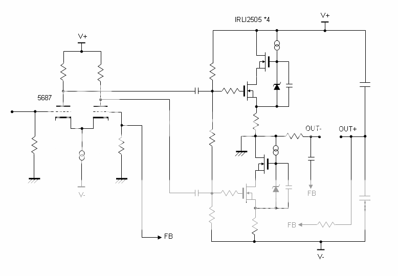
It's an SEPP with cascode FET and TransNova connection on the output, driven by LTP tube front end. Just a rough sketch right now. I haven't figure out the details of feedback and bias setting etc.
Will this work?
Thanks for reading and any comments are welcome.
A little background: http://www.diyaudio.com/forums/multi-way/155022-low-q-woofer-ob-high-zo-amp.html
The following is my goal:
1. High output impedance, about 20 Ohm for setting the system Q of my OB speaker.
2. High output voltage, for driving the 200 Ohm LF resonance peak of my woofers, I'd like to have 70~80 Vp-p output voltage at its max.
3. Not so demanding in current output, (compared to ordanary SS amp designs) For example, 200 Ohm peak mentioned above with 80Vp-p is only 0.4A. Lower impedance loads would get less voltage due to the high Zo, thus no high current, either.
4. I'd like to utilize the parts on hand as possible, including some low voltage FET -- IRLI2505, surplus spare part which was used on PWM output device of some electrical water pump in my car... This FET has a rated Vdss only 55V, and I don't even know if it can be used in audio amplfier, oh well...
5. As simple as possible. This is my first SS discrete power amp project
After reading various circuit designs, I put the peices together like this:
It's an SEPP with cascode FET and TransNova connection on the output, driven by LTP tube front end. Just a rough sketch right now. I haven't figure out the details of feedback and bias setting etc.
Will this work?
Thanks for reading and any comments are welcome.
Yes, CLS, it should work OK, but because the lower half is used in common source and the upper as a source follower, you should drive the lower half with a much lower amplitude signal, off a tapping on the plate load, adjusted for lowest second harmonic output at the speaker.
Best to do this with a distortion meter....
Hugh
Best to do this with a distortion meter....
Hugh
Thanks for reply, Hugh
After more search on the forum, I found cascode seems not a good idea. And the LTP phase splitter is not easy for me to get right. I dug out a pair of small line stage transformers (LL1582), which might be useful.
I revised the schematic:
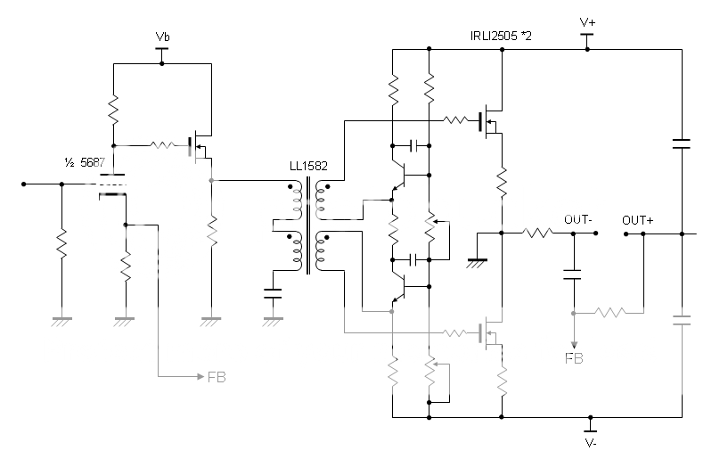
This tiny trafo can't take any DC on its windings, and the rated source impedance is 10 Ohm, so I added a buffer stage in front of it and a coupling cap. It's limited at 'only' 30dBU of its max. level, but I think this should be OK because the downstream TransNova doesn't need big voltage swing to drive.
Is this version any better?
After more search on the forum, I found cascode seems not a good idea. And the LTP phase splitter is not easy for me to get right. I dug out a pair of small line stage transformers (LL1582), which might be useful.
I revised the schematic:
This tiny trafo can't take any DC on its windings, and the rated source impedance is 10 Ohm, so I added a buffer stage in front of it and a coupling cap. It's limited at 'only' 30dBU of its max. level, but I think this should be OK because the downstream TransNova doesn't need big voltage swing to drive.
Is this version any better?
Sorry for the dumb question.
How can I figure out the driving current requirement for the output stage? It seems somewhat problematic here...
The input capacitance (Ciss) of that IRLI2505 is very high at 5000pF ! (and the transconductance is 59S) And then because of the TransNova connection, now the voltage gain of the output stage is related to the load impedance -- higher the low impedance, higher the gain.
So, am I in trouble on the Miller effect?
CLS,
My pleasure to contribute. Some interesting concepts there.
You must decide whether you want a quasi-complementary operating in Class AB, or a single ended push pull operating in Class A. The former requires a quasi-comp drive, with a bias generator and an npn and pnp driver which also fix the bias current, whilst the latter needs a follower at the upper rail, as you have, with gate biased for 0V at idle at the output, and a CCS at the lower rail, which needs only constant biasing for quiescent current with no signal drive.
If the Class AB quasi, you should consult the Quasi thread on the SS forum to see how it has been achieved in the past. You can refine this approach to the Baxandall diode for very good results and high efficiency.
If the Class A approach, the lower output device fixes the quiescent current, using a voltage reference (LED, or even a small npn device with sense resistor) but requires no signal drive.
Of the two approaches, the AB delivers power and good sound quality, the A magnificent SQ with low power and very high dissipation. I really would stick with a tube front end for this circuit, as it adds an indefinable musicality which is very appealing.
The existing bias network you have is rather complex, not necessary.
Hugh
Thanks again, Hugh
I appreciate your guidance very much. As mentioned, this is my first discrete SS power amp project And, I'm afraid my real understanding in these circuits is far less than you'd expect It seems this is going beyond what I can handle -- a strange amp with too many limitations in available parts.
I think what I want is a quasi-complementary Class AB, instead of Class A SEPP. See, I didn't know what I was talking. What an ignorant topic.
I owned and used an amp with simliar circuit (AFAIK) -- Kinergetics KBA-75. It was advertized as 75W class A, but in fact it goes class AB above 20W or so (or lower). Nevertheless, it's still an excellent amp for bass in my active system. (I gave it away about 2 years ago, sadly... )
By "quasi-complementary", I found this: Quasi-Complementary 200Watts Power Amp Schematics
quoted from above:
<The key is in Q8. Sometimes called a "complementary phase splitter", it is actually more of a level shifter. >
Do I have to do it this way? (oh, the schematic looks almost identical to the KBA-75... )
Or, something similar to this: (in which I can utilize my transformer)
http://ozvalveamps.elands.com/playmaster/pm125-2pcircuit.jpg
Would it be possible for me to steer my design towards this?
By the way, the FET I want to use - IRLI2505, has a very low threshold voltage (1.3V). It seems a little too sensistive to bias. Is there a good way to make the bias as stable as possible?
I appreciate your guidance very much. As mentioned, this is my first discrete SS power amp project
And, I'm afraid my real understanding in these circuits is far less than you'd expect It seems this is going beyond what I can handle -- a strange amp with too many limitations in available parts.I think what I want is a quasi-complementary Class AB, instead of Class A SEPP. See, I didn't know what I was talking. What an ignorant topic.
I owned and used an amp with simliar circuit (AFAIK) -- Kinergetics KBA-75. It was advertized as 75W class A, but in fact it goes class AB above 20W or so (or lower). Nevertheless, it's still an excellent amp for bass in my active system. (I gave it away about 2 years ago, sadly... )
By "quasi-complementary", I found this: Quasi-Complementary 200Watts Power Amp Schematics
quoted from above:
<The key is in Q8. Sometimes called a "complementary phase splitter", it is actually more of a level shifter. >
Do I have to do it this way? (oh, the schematic looks almost identical to the KBA-75... )
Or, something similar to this: (in which I can utilize my transformer)
http://ozvalveamps.elands.com/playmaster/pm125-2pcircuit.jpg
Would it be possible for me to steer my design towards this?
By the way, the FET I want to use - IRLI2505, has a very low threshold voltage (1.3V). It seems a little too sensistive to bias. Is there a good way to make the bias as stable as possible?
- Status
- This old topic is closed. If you want to reopen this topic, contact a moderator using the "Report Post" button.
- Home
- Amplifiers
- Solid State
- Hybrid SEPP Cascode TransNova High Zo Amp