Hi guys. I know that tone controls are a sacrilege but sometimes the sound just needs to be messed with a little.
So I've built this circuit using OPA602's and although it works perfectly on the computer; when it comes to real life there's a problem. The tone control part of the circuit (U2 and surrounding bits) is creating a -12V DC offset.
If anybody can offer any tips or solutions it would be much appreciated.
Attachments
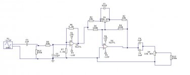
It's a drawing error, the negative rails are -15V. And like I said the simulation works fine, it's the real life circuit that's troubling me. I've gone over it with a magnifying glass and there are no bridges between tracks and the circuit is the same as the simulated one (with the addition of 100nF caps on the supply pins)
Well, it would help us to help you if we saw the circuit. I mean your breadboarded version. So far everything in your schematic seems OK, however, I am guessing that in place of R2 and R3 there should be capacitors which are different by a decade (example: 0.01uF and 0.1uF). I suggest you disconnect the first stage from the second stage and check the DV levels at OUTPUT of U1 and the input pins of U2.
my 2cents
my 2cents
alrighty, here's some (blurry) pics I took with my webcam. The feedback resistors are soldered underneath. The output of U1 is perfectly fine, there's no dc offset and the signal is nice and clean, it's only during the 2nd stage that things get messy.
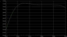
The output of low frequencies is ok, but anything about 1kHz is pretty ugly (as shown in two oscilloscope pics)
The output of low frequencies is ok, but anything about 1kHz is pretty ugly (as shown in two oscilloscope pics)
Attachments
![Picture_005[1].jpg](/community/data/attachments/126/126603-aa3ebf28eece048f3bc9ec4c6c907a36.jpg)
![Picture_008[1].jpg](/community/data/attachments/126/126608-0f8b0358d143e65e88cb8ec9549c991a.jpg)
![Picture_009[1].jpg](/community/data/attachments/126/126610-3b883e075cd1cad51631d86f86c62078.jpg)
![Picture_010[1].jpg](/community/data/attachments/126/126614-27fa0561b00af8aca39eaacba43e68de.jpg)
![Picture_012[1].jpg](/community/data/attachments/126/126620-4a1df03dc08cf7f15e16d7b8f6c734b4.jpg)
hi Oliphant,
thank you for posting pictures so quickly. But they are hard to look at, webcams aren't too good for close-ups. Anyway. From what I can tell, it seems as though (but I can't know for sure) you are using pin 8 of the OPA602ICs. Is that right? Or does it just look like on pin of the yellow capacitor is going there...? I'd find it curious that you would have the first stage wired up correctly and the second stage all of the sudden having this blatant mistake. As you know the OPA602 is of the single op-amp family meaning supply pins are 4 and 7, not 4 and 8. One thing I noticed is that you seem to have no electrolytic capacitors on your bipolar supplies, only the small yellow tantalums. I suggest you install at least a 4,7uF on each of the supply rails.
That's all I can think of for know except asking you where your original design came from.
Hmmm... I had a feeling this "DiFET" opamp could cause problems similar to the TL series. Because that opamp is special in the sense that it has a cascode input stage. It probably doesn't like to be pulled to ground.
The opa134 on the other hand, is a simple FET input opamp, much like the TL series. HOWEVER, its maximum input range is 2,5volts lower than the supply rails. (Meaning in your case, -12,5V to +12,5V).
Glad it's working for you now.
The opa134 on the other hand, is a simple FET input opamp, much like the TL series. HOWEVER, its maximum input range is 2,5volts lower than the supply rails. (Meaning in your case, -12,5V to +12,5V).
Glad it's working for you now.
Hi gain-wire. I'm using pins 4 & 7. I'll give your tip of putting 4.7uF caps on each supply next to each op amp a go and see if that increases stability. The circuit is under control for now using opa602's on the gain stage and opa134's for the tone part. The tone part of the circuit came out of an electronics magazine from the mid 90's that I've since lost
- Status
- This old topic is closed. If you want to reopen this topic, contact a moderator using the "Report Post" button.
- Home
- Amplifiers
- Solid State
- Simple Preamp with tone control problem.