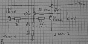
The constant current source in the attached schematics is part of my quite common lin three-stage class B amplifier design. It's supposed to feed the input stage (Load 1, LTP), and the VAS stage (Load 2, darlington paired 2SD669). There's also a bootstrap capacitor (47uF) connected between the +70V rail and the junction between resistors R4 and R5, I forgot to draw this in the schematics.
The problem is that the R1 resistor, which is supposed to set the quiescent current of the VAS at approx 6.7 mA (0,67V/100R). As I've drawn into the schematics, I measured the voltage across R1 to be only 134mV.
The next problem is that the transistor Q1 is turned hard on making it drop only 6mV across its collector and emitter (Vce). This leads to the high-side ouput device (2SK1058) being turned hard on as well, while the low-side device (2SJ162) is hard off. I measure a DC voltage of 20V at the output of the amplifier...
I didn't draw the entire schematics because I believe the error can be found somewhere within the CCS drawn here. Anyone see any obvious design flaws? I attempted to remove R2 and R6 because some designs have and some don't have these resistors in place, but it didn't make any difference.
Attachments
Elvee,
No. The circuit in post #1 simply cannot work as intended.I'd say your VAS is not sinking a sufficient current to keep the CCS in linear mode. Maybe no current at all. Perhaps a latch-up issue caused by the entanglement of the two sources.
Could you elaborate?Elvee,
No. The circuit in post #1 simply cannot work as intended.
Attachments
Ventle,
You should post the remainder of your circuit.
As I said earlier, it is possible the VAS is stuck with its output high, paralysing the lead CCS, and consequently blocking the secondary one, thus starving the differential amplifier, and in turn the VAS. A latch-up situation.
You should post the remainder of your circuit.
As I said earlier, it is possible the VAS is stuck with its output high, paralysing the lead CCS, and consequently blocking the secondary one, thus starving the differential amplifier, and in turn the VAS. A latch-up situation.
It is a matter of requirements, tradeoffs, etc. Each case is a specific case.Elvee,
anyhow, there´s great value in applying stage currents independently.
- Status
- This old topic is closed. If you want to reopen this topic, contact a moderator using the "Report Post" button.
- Home
- Amplifiers
- Solid State
- CCS acting strange. What's wrong?