Hi all.
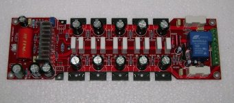
This is an amp board design from China on Ebay. It looks like a decent amp layout, but they refuse to tell me (or haven't bothered replying to me) what design it is or provide schematic with specs etc. Anyhelp would be appeciated, as I like the compact nature, while still being semi descrete design...
Here's the link:
300W LME49810 Mono channel Audio Amplifier Board - New - eBay Power Amplifiers, Amplifiers, Home Audio, Electronics. (end time 28-Nov-09 19:23:01 AEDST)
or to make it easier the picture is attached:
No doubt all the opt's and LME49810 are fake, but the desgin is more what I am interested in...
Thanks, Edddie.
Attachments
Hi all.
This is an amp board design from China on Ebay. It looks like a decent amp layout, but they refuse to tell me (or haven't bothered replying to me) what design it is or provide schematic with specs etc. Anyhelp would be appeciated, as I like the compact nature, while still being semi descrete design...
Here's the link:
300W LME49810 Mono channel Audio Amplifier Board - New - eBay Power Amplifiers, Amplifiers, Home Audio, Electronics. (end time 28-Nov-09 19:23:01 AEDST)
or to make it easier the picture is attached:
No doubt all the opt's and LME49810 are fake, but the desgin is more what I am interested in...
Thanks, Edddie.
It looks a lot like Cristi's ("cnx"), maybe a knock-off; he has been posting to the thread below for over a year. He sounds competent and friendly, although I have not bought from him ... yet. I would feel more secure buying from Cristi and Connexelectric than ebay since I can see his responsiveness with others on this site.
http://www.diyaudio.com/forums/vend...audio-amplifier-kits-modules-many-others.html
His web site has some other LME amps, some with documentation; although the 300W links seem to be broken:
edit: I posted url, but it turned into the alias, go ahead and click below:
Connexelectronic
Last edited:
if the power spply rails are only +/- 45 to +/- 60 volts you won't get anywhere near 300 to 500 watts out of it at 8ohms. Maybe 2-4ohms with 5 pairs of outputs. Probably a misprint
300W LME49810 Mono channel Audio Amplifier Board
300W Mono Channel
voltage :+-45V ~ +-60V
Size 25.5CM X 7.8CM
300W LME49810 Mono channel Audio Amplifier Board
300W Mono Channel
voltage :+-45V ~ +-60V
Size 25.5CM X 7.8CM
Be aware it appears that he is selling only the PC board and not a complete kit.
Complete amp board with all parts, as pictured.
I asked.
")
I have an old Kenwood KM 106 with +/- 68 rails, rated output is 125watts @8 ohms, at onset of clipping just a tad under 180watts @8ohms. We would need to know the voltage rating of the capacitors on board and if the output is a triple or a double. Anyways the price of the board is very reasonable esp with all the parts plus what looks like a relay switched output too!
I received one today 34 days after ordering on the 18th of November. The seller contacted me when I had not left any feedback on Ebay after several weeks. I told the seller not to worry as when the item does arrive I would leave feedback. The caps on the board are rated at 100volts so using +/- 80 or 90 volt supplies shouldn't be much of a problem. The 4.7uf input cap is paralleled with a 0.1uf wima cap. There is noted on the board that it is a LME 49810 450watt. A small schematic was included in the package as well as insulators for the output transistors. Drivers are 2sc5171/2sa1930. Outputs are 2sc5200 and 2sa1943. The schematic shows different values than what are on the board. The schematic only shows 3 output pairs while in reality there are 5 pairs. Input is shown as 1.5u ll with 0.1 but is actually 4.7uf ll with 0.1uf. A upc1237 is included on board to provide DC output protection. Because of the size of the board I don't have a heatsink that fits all 13 transistors that have to be bolted down. I have one but it need to be modified a lot. The board looks exactly like the one available at Connexelectronic. Kinda busy right now with visiting the outlaws and the holidays etc. If I have a minute or 2 to spare I will try to post some close up pics.
Last edited:
I would have to pull them off the board and test them. Hope fully when I fire up the board and run some tests the numbers will come out positively. I have bought several boards in the past from China at very low prices and all have worked fine and are still working. What I will do with these amp boards I have no idea but I am sure I will find a home for them.
sorry for reviving an old thread.
multisync , have you had more time to do some more tests on this board?
I am currently building my hifi system .1 channel and is looking for a cheap amp to use. I am currently torn between this buy or a deign with 6 x lm3886's like this one
DIY BPA300 6x LM3886 300W audio Amplifier
both should cost around the same.
I was just curious which one should be better for using on my 4 ohm load?
thanks in advance
Tang
with 4 digital camera's at home you would thing that I could take some close up photos of the boards, nope. Back to wall mart to get some more batteries. I did some 2ohm testing with +/- 42 volt power supplies, but the bridge started to smoke so I puled out a 35 year old power supply. more to follow....
ok so the boards work sort of. I powered up the boards one at a time with a 6amp? +/- 42 volt power supply. Output offset was less that 1 mvdc. Idle current was 6ma per output device, sort of. I set it to 20ma. A quick check showed that idle current varied from about 15 ma to about 30 ma across the 10 output devices, not great. A quick check of bandwidth showed very wide, a bit down at each end 5hz-110khz very good, power level was around 1 watt. Amp barely got warm at this level. Lme chip a bit warm. Took the amp to clipping and did another quick sweep. Power bandwidth about the same as low power. Heatsink started to get warm. I use 2.5 ohm 250 watt load resistors 3 in series so my load was 7.5 ohms. Tried 5 ohms at 1khz full power, heat sink got a bit warmer, tried 2.5 ohms still warmer to slightly hot. Took the freq to 100khz at 2.5 ohms at full power. Heat sink got toasty warm and I smelled something burning. The 6 amp bridge was smoking and then the output zobel resistor fell of the board. It was red hot and melted the fuse holder right beside it. At 100khz the zobel capacitor has an impedance of about 16 ohms. With the resistor in series for a total of 26 ohms. At this freq and load the output voltage was around 21 volts AC which gives a current of about 800ma going thru a 10 ohm 1/2 watt resistor which will turn red. ie the 1/2 watt resistor was trying to dissipate 6.4 watts. The amp still runs. I replaced the resistor. After some more testing I thought I saw some fuzzines on the positive peaks of the output waveform. Sure enough a bit of oscillation. I used the 3.3kohm and 75 pf fix posted elsewhere and that was that. Next test I will fire up my nearly 40 year old power supply. +/-56 volts at 10 amps, 20 amps if I don't run it too long, the trannys get a bit warm They are old hamond 210s. 22 pounds each, one for the + and one for the -. more to follow and maybe some pics. Oh yeah both boards needed the fix.
the biggest delay in posting results was trying to mount the board to a heat sink. I have tons of heat sinks, almost all are for T03 devices. I have only a couple that don't have fins on both sides. It took me a long while to drill and tap 13 f'ing holes to line up with 10 power transistors the 2 drivers and the vbe multiplier. Much swearing and broken taps. Ebay is my friend as none of the big box stores sell small taps with drill bits to match
the +/- 60 volt goes to the LME chip and the +/- 45 is fused and goes to the power transistors. I have the 2 tied together right now , I may use small resistors ie 10 ohm or less between the 45 and 60 volt lines or diodes or separate PS, in the final set up or nothing I haven't decided yet. I will try to do some distortion testing, my old heathkit Ig18 has been extensively moded but the lowest it goes is .016% (10 times better than new) which is very near the limit of my Hp 334. The lme is supposed to be at least 10 times better.(lower). I think the intent was to provide a low ripple/regulated power line for the lme chip and a high current unregulated for the outputs. by the way I also have a couple of the Bp300 boards. They are pretty much bullet proof. Over temp over load excessive current short circuit etc. Depending on your desired power output and parts source a low voltage high current transformer and caps are easier to get rather than a high voltage high current transformer and caps. You need at least +/- 55-65 volts dc to get 200watts at 4 ohms (80-90volts ac center taped) depending on power supply reserve. With a bp300 bridged setup you would need +/- 35volts dc droping down to +/- 25-30 volts dc under load. to get 200 watts at 4 ohms. Using the +/- 42 volt power supply I mentioned above I was able to get 72 watts at 8 ohms clipping and just over 110 @ 5 ohms with one bp300 board ie 3 lm3886 chips in parallel. With this setup theoretically I should be able to push a pair of bp 300's to 300-400 watts if the power supply holds( 6 x 68 watts per chip maximum) and the heat sinks are large enough. I had to replace all of the power supply caps on the bp 300 boards as they were only rated at 35volts. I increased them to 50 volt caps. Nobody runs their amps at clipping continuously at home. Most decent uncompressed music has at least 20db peaks ( x10) . So you should be able to push the chips to near max for your project.
Thanks!
I basically did the same math and concluded that i am going to bridge the two boards with 3 x lm3886's. I actually ordered the pc boards yesterday
I also did the math with 35V vs 65V power supply's and came to the conclusion that the capacitors is going to be the only real cost difference. but it is going to be a bit.
I have built a few lm3886 amplifiers ,and hoped that I had a reason to play with solid state for this project. But it seems that chipamps are the easiest/cheapest and possibly safest option.
Thanks again for your help.
Hi multisync
"I used the 3.3kohm and 75 pf fix posted elsewhere and that was that"
If is not to much trouble can you post the schematic and where you place the fix?
1/2 watt zobel resistor.....as far as i know it should be at least 3 w for safe operation.
Does the output coil have a resistor in parallel with it? I can't see from the pictures.
Do you think this amplifier will work fine at 2x80 V CC/8 omh speaker?
Your feedback is much appreciated!
- Status
- This old topic is closed. If you want to reopen this topic, contact a moderator using the "Report Post" button.
- Home
- Amplifiers
- Solid State
- Anyone recognise this Design..? based on LME49810