Duo said:The transistors are about $4.00 each.
Ah. From where? The Toshibas that Digi-Key is selling are considerably less than that. Or are you talking Canadian dollars or something?
Are you looking to build a one-off amp just for yourself or will this be a commercial venture? If you're just doing this for yourself, I could sell you some Motorolas for cost plus shipping. We buy 'em by the thousand.
se

Need power?
Hi Duo.
Take a little peek over these schematics:
http://www.qscaudio.com/support/library/schems/rmx4050.pdf
You can very easy get 1300W on 4 Ohms load with only....6 pairs of 2SC5200/2SA1943.
In bridge mode you can get 4000W/4 Ohms load!
This is a factory model,so don't forget about "All rights reserved"
and that kind of stuff.I think the guys wouldn't complain if you
"steel" it for your own needs and don't distribute it.
The project is a little bit complex on the first look,and I don't
recommend it for those with less experience.
I'm working on the PCB,so when I finish it I will show you if you
are interested.
Regards.")
Hi Duo.
Take a little peek over these schematics:
http://www.qscaudio.com/support/library/schems/rmx4050.pdf
You can very easy get 1300W on 4 Ohms load with only....6 pairs of 2SC5200/2SA1943.
In bridge mode you can get 4000W/4 Ohms load!
This is a factory model,so don't forget about "All rights reserved"
and that kind of stuff.I think the guys wouldn't complain if you
"steel" it for your own needs and don't distribute it.
The project is a little bit complex on the first look,and I don't
recommend it for those with less experience.
I'm working on the PCB,so when I finish it I will show you if you
are interested.
Regards.
Yeah, I guess 6 of those will work. I just ordered 10 pairs of MJ21193/MJ21194 transistors as samples from onsemi. They do 16A @ over 200V a piece. Nice transistors, and being Motorola, they would be quite nice.
Do you suppose I could use 5 pairs of these Motorola transistors?
I'm think that 5 pairs of them should do quite a bit. If they don't suffice for 2000W, then at least they should come quite close.
Do you suppose I could use 5 pairs of these Motorola transistors?
I'm think that 5 pairs of them should do quite a bit. If they don't suffice for 2000W, then at least they should come quite close.
Interesting design these guys use. However, I detest opamps. I might steal some ideas from the output stage and driver arrangement and use them myself after some alterations. I see how they're designing the amp and I like the output stage a lot. It's actually very similar to the design I'm using.
The output stage in my amp uses the same topology as that in the ESP 3A, and the P68. The amps use compound emitter followers and current sink bias arrangements. I like the way that topology sounds, especially with its inherent simplicity.
The construction of such an output stage is very simple and doesn't require many parts. The bias is simple as well.
Anyway, I'll keep conceptualizing for now.
BTW: How much power does the next lower model of RMX amp produce? I looked at its design with the four output pairs and that is easy to do...
Duo said:Steve: Yes, I'm ordering in Canadian currency. If you have motorolas for sale I'm interested is they're not too expensive. How much would is cost me for 40 pairs of transistors?
We're paying about $2US a pop. I don't keep up on the day-to-day stuff and apparently we're working on a big pile of stuff for InnerSound and Doug's not willing to part with 40 pair at this time. Sorry 'bout that. I'll try and remember to see how things stand in a few weeks. Feel free to give me an EMail reminder if you'd like.
se
Toshiba or Motorola?
Hi Duo.
Yes,you can replace them with Motorola transistors.Putting 5 pairs instead of 6 pairs is not a good solution.Motorola transistors can dissipate more power but we are talking about 4KW in bridge mode!The calculations allows 5 pairs if you don't bridge the amps.
My choice is Toshiba's transistors.By the way,wy the QSC guys didn't use Motorola devices?Better characteristics?Think about it.
About the OP Amps in the input stage...I agree with you.It's not the best,but it isn't the bad solution.I have a couple projects with OP Amps and they never failed me.
As you said the output stage is interesting.The good thing is that you can mount the output devices directly on the heatsink without using mica washers.The transistors can dissipate more power!Of course the heatsinks must be isolated from the chassis.
I had a opportunity to listen this beast and I couldn't belive how much sound pressure it can produce!
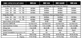
I've attached some RMX specs.The RMX2450 uses 4 pairs per channel,as you asked.
Regards friend.
Hi Duo.
Yes,you can replace them with Motorola transistors.Putting 5 pairs instead of 6 pairs is not a good solution.Motorola transistors can dissipate more power but we are talking about 4KW in bridge mode!The calculations allows 5 pairs if you don't bridge the amps.
My choice is Toshiba's transistors.By the way,wy the QSC guys didn't use Motorola devices?Better characteristics?Think about it.
About the OP Amps in the input stage...I agree with you.It's not the best,but it isn't the bad solution.I have a couple projects with OP Amps and they never failed me.
As you said the output stage is interesting.The good thing is that you can mount the output devices directly on the heatsink without using mica washers.The transistors can dissipate more power!Of course the heatsinks must be isolated from the chassis.
I had a opportunity to listen this beast and I couldn't belive how much sound pressure it can produce!
I've attached some RMX specs.The RMX2450 uses 4 pairs per channel,as you asked.
Regards friend.
Attachments
Hmmm, Interesting ideas. I think I'll stick to my own design. I'm happy with it. I think for now I'll just use the 5 pairs of motorola. That'll still get me into 1000W @4ohms which should be plenty for our rental house. I mean, how much SPL could I need? lol.
I do see that the frequency of the Motorola devices is lower, but they are more linear. They should work fine in audio if I have sufficient drive current...
I do see that the frequency of the Motorola devices is lower, but they are more linear. They should work fine in audio if I have sufficient drive current...
Hi.
Well,I didn't say that Motorolas is a bad choice and a matter of fact I would be very happy with them.But if I have to choose between them I would choose Toshiba's.For a example:
I've built two identical amps with different output transistors.The
difference was obvious.The Toshiba transistors sounds better!
Some of my local experts agrees with me.
You can very easy get 1300W on 4 Ohms load with only....6 pairs of 2SC5200/2SA1943.
In bridge mode you can get 4000W/4 Ohms load!
lol
That means the amp can handle
2 ohm load (non-bridged) if 4 ohm bridged.
It common to see exagerrated claims.
I can run my Adcom 555 bridged
@ 1 ohm load ! Only if I run an array
of tweeters, trying doing this with
woofers operating at low frequencies
and "yikes".. nay worky... barf.......
Nobody knows how ratings are established, did they measure 4kw
for 1 second or did they run the amplifier at 4kw @ 1khz ? From
the looks of the spec sheet, they
used 1khz... boring!
Did they run the amplifier all day to see if it's stable ? Try running those 6 pairs at 20hz driving 4 ohm woofer array and see if it likes it.
To be or not to be...
Hi.
These are factory specs.I didn't made them up.We all know that these values are for marketing reasons!
Of course it's not recommended working on 4 0hms in bridge mode!Probably they measured this in a short term.But...as you see,amp can deliver 2600W at 8Ohms bridged.I think this is quite enough
After all,I'm finishing the PCB soon and I will perform some hardcore testings.
Regards.
Attachments
By the way folks here are some usefull things about power ratings:
http://www.polkaudio.com/home/faqad/advice.php?article=pwrratings
http://www.polkaudio.com/home/faqad/advice.php?article=pwrratings
Number one, the QSC has ±47V, ±94V, and ±141V with six 30,000µF caps per channel. Without these there is no way 6 pairs of plastic transistors will do whatever this thing is rated at.
Did you look at those four 52A rail switches, all the floating ± supplies for the 311 comparators? For each channel? Ignoring the low current ± supplies, this thing has 6 high current bridge rectifiers and 24 pcs of 15,000µF filter caps. Have fun getting the transformer made.
Unless you do a multi-tiered supply, bridge amp, or a fully regulated supply, there is no way to get 1000W/4R from a 200V transistor.
A Crown VZ5000 does 2000W/4W in stereo, and can drive a 2R load if needed. All that is needed is a 55-0-55V transformer, one bridge rectifier, and one pair of 10,000µF/100V filter caps. It is a bridge design, as most Crown amps are, and uses four pair of MJ21193/94 per half; eight pair per channel total. These are USD$2.00 each. The Crown uses one rail switch per channel as contrasted with the four that the QSC uses.
Cool, that Crown design is very much like what I was planning on doing. My transformer is exactly 55-0-55 VAC and I have the recifiers for it, and caps. How much power do you figure I'd get running one channel (not bridged) with the 55-0-55 tranny and 5 pairs of MJ21193/21194??
- Status
- This old topic is closed. If you want to reopen this topic, contact a moderator using the "Report Post" button.
- Home
- Amplifiers
- Solid State
- Ideas for parts in insanely powerful amp?