Hi folks,
Dropped the stylus on the old vinyl and...nothing. Figured out it was the amp(BK St202), pulled the top and started snooping.
Visual inspection showed the left channel biasing(?) LED flashing intermittently before stabilizing, and the right channel LED off altogether.
Next, I measured the voltage coming off of the rails(this is where I become confused). Both rails show the proper voltage at one side of the power supply fuses( -66V & +65.5V). However, on the other side of the fuses, and also on the main board, I read 28V for both V- rails(instead of -66V) and +65.5V for the left channel V+ BUT 28V for right channel V+.
Given that the two output boards are separate for each channel, I think that it's a PSU problem. Have the schematic for the driver/output boards but not the PSU(which looks pretty basic at first blush...although it's mounted upside-down and directly to the filter caps so I can't actuall see the components.
Any recommendations on where to look first?
thanks,
pete
Dropped the stylus on the old vinyl and...nothing. Figured out it was the amp(BK St202), pulled the top and started snooping.
Visual inspection showed the left channel biasing(?) LED flashing intermittently before stabilizing, and the right channel LED off altogether.
Next, I measured the voltage coming off of the rails(this is where I become confused). Both rails show the proper voltage at one side of the power supply fuses( -66V & +65.5V). However, on the other side of the fuses, and also on the main board, I read 28V for both V- rails(instead of -66V) and +65.5V for the left channel V+ BUT 28V for right channel V+.
Given that the two output boards are separate for each channel, I think that it's a PSU problem. Have the schematic for the driver/output boards but not the PSU(which looks pretty basic at first blush...although it's mounted upside-down and directly to the filter caps so I can't actuall see the components.
Any recommendations on where to look first?

thanks,
pete
1) 2 fuses corresponding to right channel blown, replaced fuses...poof!
2) discharged caps...zap! disconnected from output
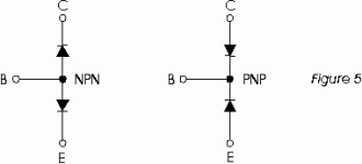
3) Checked transistors...warning, don't know a pnp from a hole in the ground. So, not knowing any better, I checked them in diode mode and found the following --
"bad channel" - 2 transistors (one from each bank) measured 0 volts. The other four measured .165 volts
"good channel" - all measured .685 volts.
That's what I have so far...any suggestions welcomed.
regards,
pete
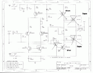
Here's the schematic. Don't know why two that are not complementary would be fried...the maid service was in yesterday, the amp was on, I'll blame them.
http://pgudaitis.home.mindspring.com/images/st_202_shematic.gif

http://pgudaitis.home.mindspring.com/images/st_202_shematic.gif
The output devices are mosfets. Upper ones are N-channel, the lower ones P-channel. Is there written 'Matched 3 pair' ?
This means two times 3 matched mosfet pairs. You'll have to keep that in mind.
Look at http://www.passdiy.com/howto/matching.htm to learn how to match them.
The drivers are normal transistors.
Upper one PNP and bottom NPN.
This and the drawing from hugobross are good sources to learn how to measure transistors and fets:
http://www.eatel.net/~amptech/elecdisc/ampfail.htm.
Your biggest problem will be finding the correct devices.
I'm not able to read the exact numbers of the devices on your schematic (could be my eyes).
You'll have to check every transistor and fet marked with a cross.
Maybe even the other ones.
Better take them out if you can.
You did a good job with the diode test, and with comparing to the other channel.
Carry on and good luck.
/Hugo
Attachments
Hi Hugo,
The mosfets are Toshiba and are marked SK405 and SJ115(3?)...and appear to be obsolete - Toshiba doesn't even make reference to them. Thus, I need to find some way of finding suitable replacements, and buying enough to match and replace all on both boards.
I'm hesitant to do this because I still don't know what caused the meltdown in the first place. I'll pull the bad board and measure what I can to see if anything upstream seems suspicious.
Irony of ironies, I just recieved the parts to make an LM1875 Gainklone. If it had worked out, I was going to sell this amp.
thanks for all of your help - and the links.
pulling tubes is much easier.
pete
The mosfets are Toshiba and are marked SK405 and SJ115(3?)...and appear to be obsolete - Toshiba doesn't even make reference to them. Thus, I need to find some way of finding suitable replacements, and buying enough to match and replace all on both boards.
I'm hesitant to do this because I still don't know what caused the meltdown in the first place. I'll pull the bad board and measure what I can to see if anything upstream seems suspicious.
Irony of ironies, I just recieved the parts to make an LM1875 Gainklone. If it had worked out, I was going to sell this amp.

thanks for all of your help - and the links.
pulling tubes is much easier.
pete
pedroskova said:Thus, I need to find some way of finding suitable replacements
pete
I can still buy matched pairs of 2SK405/J115. They come as a set and cost €18 without transport.
You also could try finding the 2SK1529 and the 2SJ200.
They could do the job.
/Hugo
djk said:What a bogus design, no gate protection zeners.
Farnell sells them, about $10 in one lot qty.
Actually, they have a number of diodes in the circuit - they're just not shown in that scan. I have another more detailed schematic, but it would have had to have been very large to be readable.
Are they "gate protectors"? I wouldn't have a clue.
pete
- Status
- This old topic is closed. If you want to reopen this topic, contact a moderator using the "Report Post" button.
- Home
- Amplifiers
- Solid State
- Troubleshooting dead amp...Help


