Here is a little investigation of mine into the elimination “VAS” distortion in symmetrical “single stage” amplifier topologies. By the VAS stage I mean the common-base (folded cascode) stage used in these designs.
I’ve been experimenting with the folded cascode VAS for both a current feedback design (a power output stage with negative feedback) and a voltage feedback front-end design, with the conventional complementary LTP input stage.
I was initially unimpressed with the linearity performance of the folded cascode stage, as in all cases it had, at minimum, an order of magnitude worse linearity than a buffered common-emitter VAS (as in the “Blameless”) linearized with local feedback provided by Cdom
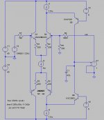
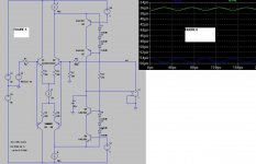
The first attachment entitled “figure1” is the basic voltage feedback, folded cascode circuit, simplified for simulation purposes to isolate what I have found to be the major source of distortion.
The amplifier has a closed loop gain of 20 and a unity loop gain frequency of approximately 700kHz, the frequency compensation being provided by the 47pF shunt compensation capacitor C1. The LTP is run at a healthy tail current of 5mA and is heavily linearized by the emitter degeneration. The VAS quiescent current is defined by I1 and I3, and is 5mA.
The folded cascode VAS is buffered with an ideal unity gain VCVS and I am driving the circuit with a 1V peak sinewave input to generate a 20V peak output.
At any audio test frequency the linearity is literally woeful, for example:
1kHz
0.001364%
20kHz
0.011918%
At 20Vpeak output, the peak drive current required, as dictated by the 47pF compensation capacitor, C1, is only 120uA peak.
This is a rather small current swing required of the complementary LTP input stage with its tail current of 5mA and heavy degeneration.
The poor linearity performance therefore cannot be attributed to the LTP or any excessively demanding drive requirements of the compensation scheme.
The answer to the poor linearity performance lays in the folded cascode VAS transistor base current.
Taking the figure 1 circuit as an example, as previously explained the VAS has a quiescent current of 5mA and the peak signal current at 20kHz is only 120uA.
Under these circumstances the non-linearity incurred by the variation of Ic is truly negligible. However, the hfe variation with Vce combined with feedback Via Cob is not negligible in the least, and this should not surprise, as the full output voltage swing is presented to the collector of each folded cascode transistor.
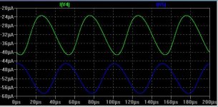
The (non-linear) base currents of these transistors are shown in the second attachment, entitled figure2, at 20kHz.
There is ~20uA DC imbalance due to the difference in Hfe between the PNP and the NPN transistor, however this can be ignored at this point as it isn’t a significant imbalance for a circuit with a 5mA quiescent current. What is much more important is the ac component which is very non-linear and in the order of ~15uA p-p ; a very significant amount in comparison to the 120uA peak current being delivered to C1.
The cause of the poor linearity of the folded cascode VAS is now obvious. At this point the solution to the problem should also be obvious; the folded-cascode transistor pair needs to be cascoded to reduce (as much as possible) the variation of Vce – but this is not necessarily so straight forward!
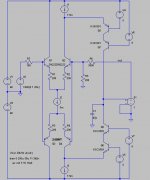
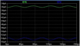
Attachment Figure3 shows an attempted solution – the folded cascode transistors (Q5 and Q6) are cascoded, with their Vce fixed reasonably well at 3V. Figure4 shows the base currents of these transistors now, with the cascodes.
This is obviously looking a great deal more rosy than previously in Figure2, with the non-linear ac component being reduced to approximately 1uA peak-to-peak.
What is more important than this significant reduction in ac amplitude, though, is that the base currents are far more linear with respect to Ic than before, as the non-linear component fed back via Cob has been eliminated by the cascoding.
Unfortunately, though, the pooch has been screwed in a major way. While the base currents of Q5 and Q6 are now in much, much better shape, we now have the exact same base current problem as before, it has just been shifted to the cascode transistors. D’oh!
In fact, theory says that the overall linearity should now be worse, as we now have the (essentially) unchanged base current issue shifted from to the cascode transistors added to the reduced base current issue of the folded-cascode transistors.
This is confirmed in simulation:
1kHz,
0.001468%
20kHz
0.014487%
What to do? Enter the attachment entitled Figure 5
The more astute out there will instantly recognise this as the “Hawksford cascode” applied to a folded cascode VAS. However, the magic of this circuit may not be immediately obvious.
The cascode transistors are each biased by a string of three 1n4148 diodes, the diodes being forward biased with a current of 2.5mA as set by the 27k resistor, R8. Current sources I1 and I3 have been increased by 2.5mA each, to 10mA, to restore the quiescent VAS current to 5mA.
Now back to the magic of this circuit. Just as in the previous circuit, the cascode transistors still have the full output voltage swing presented to their collectors, and they still have that horrible non-linear ~15uA of base current at 20kHz – but this base current is kept in the loop.
Without getting too boringly analytical (you can do that yourself), the base current of cascode transistor Q7 is subtracted from the emitter current of Q5, and the same goes for the other pair, transistors Q6 and Q8.
Figure 6 shows the base new currents of the folded cascode transistors, Q5 and Q6. As you can see, amplitude wise, it’s pretty much identical to the cascoded results achieved previously which is what one should expect.
however, the cascode transistor base current issue has been addressed, and theory says that the circuits linearity should be literally transformed, as the folded-cascode VAS distortion is now pretty much eliminated.
Does the simulator agree with theory?
1kHz
0.000006%
20kHz
0.000077%
Yep!
I’ve presented a simplified case here, just to demonstrate the dominant issue of the VAS non-linearity and how to solve it. I’ve tested this in complete (complex) design simulations and the results are perfectly repeatable in every case.
There is another very important issue regarding getting the best possible linearity from the folded-cascode topology, and that is keeping the non-linear loading on the VAS collector (output) as light as possible, but that is a topic for another day.
Basically, the Hawksford cascode has proven its worth not only on a conventional common-emitter VAS (as originally described in his “Slope Distortion” paper), but on the folded-cascode VAS as well (but not for the entirely same reasons!)
Cheers,
Glen
I’ve been experimenting with the folded cascode VAS for both a current feedback design (a power output stage with negative feedback) and a voltage feedback front-end design, with the conventional complementary LTP input stage.
I was initially unimpressed with the linearity performance of the folded cascode stage, as in all cases it had, at minimum, an order of magnitude worse linearity than a buffered common-emitter VAS (as in the “Blameless”) linearized with local feedback provided by Cdom
The first attachment entitled “figure1” is the basic voltage feedback, folded cascode circuit, simplified for simulation purposes to isolate what I have found to be the major source of distortion.
The amplifier has a closed loop gain of 20 and a unity loop gain frequency of approximately 700kHz, the frequency compensation being provided by the 47pF shunt compensation capacitor C1. The LTP is run at a healthy tail current of 5mA and is heavily linearized by the emitter degeneration. The VAS quiescent current is defined by I1 and I3, and is 5mA.
The folded cascode VAS is buffered with an ideal unity gain VCVS and I am driving the circuit with a 1V peak sinewave input to generate a 20V peak output.
At any audio test frequency the linearity is literally woeful, for example:
1kHz
0.001364%
20kHz
0.011918%
At 20Vpeak output, the peak drive current required, as dictated by the 47pF compensation capacitor, C1, is only 120uA peak.
This is a rather small current swing required of the complementary LTP input stage with its tail current of 5mA and heavy degeneration.
The poor linearity performance therefore cannot be attributed to the LTP or any excessively demanding drive requirements of the compensation scheme.
The answer to the poor linearity performance lays in the folded cascode VAS transistor base current.
Taking the figure 1 circuit as an example, as previously explained the VAS has a quiescent current of 5mA and the peak signal current at 20kHz is only 120uA.
Under these circumstances the non-linearity incurred by the variation of Ic is truly negligible. However, the hfe variation with Vce combined with feedback Via Cob is not negligible in the least, and this should not surprise, as the full output voltage swing is presented to the collector of each folded cascode transistor.
The (non-linear) base currents of these transistors are shown in the second attachment, entitled figure2, at 20kHz.
There is ~20uA DC imbalance due to the difference in Hfe between the PNP and the NPN transistor, however this can be ignored at this point as it isn’t a significant imbalance for a circuit with a 5mA quiescent current. What is much more important is the ac component which is very non-linear and in the order of ~15uA p-p ; a very significant amount in comparison to the 120uA peak current being delivered to C1.
The cause of the poor linearity of the folded cascode VAS is now obvious. At this point the solution to the problem should also be obvious; the folded-cascode transistor pair needs to be cascoded to reduce (as much as possible) the variation of Vce – but this is not necessarily so straight forward!
Attachment Figure3 shows an attempted solution – the folded cascode transistors (Q5 and Q6) are cascoded, with their Vce fixed reasonably well at 3V. Figure4 shows the base currents of these transistors now, with the cascodes.
This is obviously looking a great deal more rosy than previously in Figure2, with the non-linear ac component being reduced to approximately 1uA peak-to-peak.
What is more important than this significant reduction in ac amplitude, though, is that the base currents are far more linear with respect to Ic than before, as the non-linear component fed back via Cob has been eliminated by the cascoding.
Unfortunately, though, the pooch has been screwed in a major way. While the base currents of Q5 and Q6 are now in much, much better shape, we now have the exact same base current problem as before, it has just been shifted to the cascode transistors. D’oh!
In fact, theory says that the overall linearity should now be worse, as we now have the (essentially) unchanged base current issue shifted from to the cascode transistors added to the reduced base current issue of the folded-cascode transistors.
This is confirmed in simulation:
1kHz,
0.001468%
20kHz
0.014487%
What to do? Enter the attachment entitled Figure 5
The more astute out there will instantly recognise this as the “Hawksford cascode” applied to a folded cascode VAS. However, the magic of this circuit may not be immediately obvious.
The cascode transistors are each biased by a string of three 1n4148 diodes, the diodes being forward biased with a current of 2.5mA as set by the 27k resistor, R8. Current sources I1 and I3 have been increased by 2.5mA each, to 10mA, to restore the quiescent VAS current to 5mA.
Now back to the magic of this circuit. Just as in the previous circuit, the cascode transistors still have the full output voltage swing presented to their collectors, and they still have that horrible non-linear ~15uA of base current at 20kHz – but this base current is kept in the loop.
Without getting too boringly analytical (you can do that yourself), the base current of cascode transistor Q7 is subtracted from the emitter current of Q5, and the same goes for the other pair, transistors Q6 and Q8.
Figure 6 shows the base new currents of the folded cascode transistors, Q5 and Q6. As you can see, amplitude wise, it’s pretty much identical to the cascoded results achieved previously which is what one should expect.
however, the cascode transistor base current issue has been addressed, and theory says that the circuits linearity should be literally transformed, as the folded-cascode VAS distortion is now pretty much eliminated.
Does the simulator agree with theory?
1kHz
0.000006%
20kHz
0.000077%
Yep!
I’ve presented a simplified case here, just to demonstrate the dominant issue of the VAS non-linearity and how to solve it. I’ve tested this in complete (complex) design simulations and the results are perfectly repeatable in every case.
There is another very important issue regarding getting the best possible linearity from the folded-cascode topology, and that is keeping the non-linear loading on the VAS collector (output) as light as possible, but that is a topic for another day.
Basically, the Hawksford cascode has proven its worth not only on a conventional common-emitter VAS (as originally described in his “Slope Distortion” paper), but on the folded-cascode VAS as well (but not for the entirely same reasons!)
Cheers,
Glen
Attachments
Last edited:
slightly off topic question.
Why does the simulator allow I2 to work? It looks like a jFET input stage but BJTs are in there.
Regarding the CCS, the simulator doesn't care what the terminal voltages are.
Thanks for the link.
Hey Andy, my in-box is open

I recall to follow article by reading this thread:
Memory Distortion Philosophies
Lavardin Technologies - distorsion de memoire
If I have time, I will comment more exactly to your observations
Memory Distortion Philosophies
Lavardin Technologies - distorsion de memoire
If I have time, I will comment more exactly to your observations
"Basically, the Hawksford cascode has proven its worth not only on a conventional common-emitter VAS (as originally described in his “Slope Distortion” paper), but on the folded-cascode VAS as well (but not for the entirely same reasons!)"
Although not quite as creative as yours, I've done quite a bit of simulation on my VAS stage and have come to exactly the same conclusion - Hawksford's VAS solution rocks. It even works great on CFA topologies - I'm using it on a CFA line pre-amp I'm working on. I'm getting similar distortion figures to you - 500ppb although my output is around 2V. This is with about 20db of feedback. with c. 8db of feedback, I'm still around .0002% at 20KHz
Although not quite as creative as yours, I've done quite a bit of simulation on my VAS stage and have come to exactly the same conclusion - Hawksford's VAS solution rocks. It even works great on CFA topologies - I'm using it on a CFA line pre-amp I'm working on. I'm getting similar distortion figures to you - 500ppb although my output is around 2V. This is with about 20db of feedback. with c. 8db of feedback, I'm still around .0002% at 20KHz
Thanks for the link.
Hey Andy, my in-box is open
Oops, didn't see this until just now. YGM
.On the Optimization of Enhanced Cascode[/url]
OK, I just read through that paper. This paper describes an improvement to the “Hawksford cascode” as applied to a symmetrical common emitter VAS, so this is a little different to what I have posted here though.
What I’ve done here it to apply the “Hawksford cascode” to the symmetrical folded cascode VAS, with rather worthwhile results. I just haven’t seen this done before so I figured it was worth detailing.
I have a play and see if Dimitri's enhanced ”Hawksford cascode” is equally beneficial when applied to this application.
Last edited:
"Basically, the Hawksford cascode has proven its worth not only on a conventional common-emitter VAS (as originally described in his “Slope Distortion” paper), but on the folded-cascode VAS as well (but not for the entirely same reasons!)"
Although not quite as creative as yours, I've done quite a bit of simulation on my VAS stage and have come to exactly the same conclusion - Hawksford's VAS solution rocks. It even works great on CFA topologies - I'm using it on a CFA line pre-amp I'm working on. I'm getting similar distortion figures to you - 500ppb although my output is around 2V. This is with about 20db of feedback. with c. 8db of feedback, I'm still around .0002% at 20KHz
Do those designs use a folded cascode VAS? Circuit?
Then you have the basic topology of the German brand "AVM"Hey, that circuit would make for a good experiment. Delete the current mirrors and replace with the folded cascode VAS.
Attachments
Circuit as promised. This has the servo included. 20KHz into 600 Ohms is 270ppb. Without thw Hawksford VAS, I struggle to smell 10ppm.
Looks YAPish
Basic, textbook CFA.
Including the much discussed diamond buffer driver
?- Status
- This old topic is closed. If you want to reopen this topic, contact a moderator using the "Report Post" button.
- Home
- Amplifiers
- Solid State
- My folded-cascode VAS linearity investigation