Hello to all,
I'm putting my hands on an old Nikko trm-750 amplifier. I like the sound of the power stage, but the preamp is a disaster. I upgraded some components (IC, capacitors and so on), stabilized the power supply, and now all run really better.
The problem is that the line stage has a too high gain, and it is putted after the Volume-Balance control. The result is an useless very high sensitivity, with an avoidable background noise and an uneasy volume regulation (you can't arrive to the half position, it's too loud).
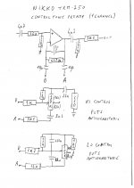
I didn't manage to find any schematics, so I taken the time to put on paper the control tone board. The result is in the attachment. I think that this kind of circuit was preferred to both baxandall negative feedback and passive circuits just to save an additional IC: with the adopted solution you don't have impedance problems, both in the input and in the output, but... changing gain is an hell! (for me, of course... )
)
Which kind of circuit is this? Giving an eye, it seems it can permit a + or - 20 dB tone control, that is waaaaaay toooo much. In this configuration, if I'm not wrong, the gain can't run below 1, so, considering this condition as the maximum tone attenuation, I'd like to transform this stage in a 6÷9 dB gain one, with the same amount of tone control (+ or - 6÷8 dB).
Sincerely, I have no skill to calculate new value, and the potentiometers must remain the same (100k, -logarithmic) for mechanical reason, so... any good soul out there that can help me??
A great hello
Max
I'm putting my hands on an old Nikko trm-750 amplifier. I like the sound of the power stage, but the preamp is a disaster. I upgraded some components (IC, capacitors and so on), stabilized the power supply, and now all run really better.
The problem is that the line stage has a too high gain, and it is putted after the Volume-Balance control. The result is an useless very high sensitivity, with an avoidable background noise and an uneasy volume regulation (you can't arrive to the half position, it's too loud).
I didn't manage to find any schematics, so I taken the time to put on paper the control tone board. The result is in the attachment. I think that this kind of circuit was preferred to both baxandall negative feedback and passive circuits just to save an additional IC: with the adopted solution you don't have impedance problems, both in the input and in the output, but... changing gain is an hell! (for me, of course...
)Which kind of circuit is this? Giving an eye, it seems it can permit a + or - 20 dB tone control, that is waaaaaay toooo much. In this configuration, if I'm not wrong, the gain can't run below 1, so, considering this condition as the maximum tone attenuation, I'd like to transform this stage in a 6÷9 dB gain one, with the same amount of tone control (+ or - 6÷8 dB).
Sincerely, I have no skill to calculate new value, and the potentiometers must remain the same (100k, -logarithmic) for mechanical reason, so... any good soul out there that can help me??
A great hello
Max
Attachments
Hi Max, to use a Baxandal tone control with a non-inverting amplifier is not optimal since the non-inverting amplifier gain is not simply the ratio setting on the pot. This is the reason why there are so many components in the tone control in that they are trying to compensate for the non symmetrical manner that the controls behave.
Changing any resistor value to change the boost/cut would also require a change in the capacitance to retain the turn-over frequency.
I would suggest that you by-pass the tone control of the amp and build the inverted tone control found in the AKSA headphone amplifier thread on a piece of vero board and then patch it into your amp.
Nico
Hi Nico, thanks a million for the replay. I suspected something similar, but sincerely I'd like to use this kind of topology. Is there a page to learn which are the interaction between components, and how to calculate values?
Just right now I discovered that the mechanical reason for the use of the pots are not so strictly, probably I can change them, so at least I can use the schematic suggested by Hugo in the Aspen headphone amp thread, post #732.
The optimum should be the same schematic with an overall gain of 10÷12 dB, but I'm not able to calculate it.
Thank you again,
Max
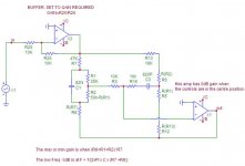
THE ATTACHED CIRCUIT WORKS WITH BOOST AND CUT = 6.02dB. THE SECOND AMP IS ABUFFER AND GAIN IS THE SAME SETTINGS AS THE POTS, IN OTHER WORDS IT HAS 0dB GAIN IF POTS ARE CENTRED.
THE FRONT END BUFFER IS SET TO THE GAIN NUMBER YOU NEED FOR THE AMP TO BE LOUD ENOUGH.
THE FRONT END BUFFER IS SET TO THE GAIN NUMBER YOU NEED FOR THE AMP TO BE LOUD ENOUGH.
Attachments
yes Nico, thanks a lot, a very useful reply to investigate in the inverting - inverting = non inverting 2 stage tone control. But I'd be very curios to know more about the non-inverting, single stage tone control.
From your answer, I understand you aren't too much involved with this configuration, so I'll not ask you any additional effort but some information (internet pages, books and so on) where I can learn more about this kind of topology (if this information are available, of course...)
Thank you a lot again, a very interesting circuit to study on
Max
Go see here, I think I explained it pretty good why the non-inverting mode is not preferred
http://www.diyaudio.com/forums/aksa/152031-aspen-headphone-amp-73.html#post1968996
Post 722, 723, 724
http://www.diyaudio.com/forums/aksa/152031-aspen-headphone-amp-73.html#post1968996
Post 722, 723, 724
Here is an extract from an e-mail to the AKSA thread, I hope this sheds more light.
Hi Nico,
Thanks for the email.
Nico Ras wrote:
>
> Tone controls should be seen as a simple single pole filters and it can be set to anything you desire. The calculations is equally simple and you can try it on your simulator. If you were just playing with values then you are in the bush because nothing will seem logical.
>
> Firstly decide on the boost and cut (usually the same to retain a simmetricl range around 0dB. This is the most usual.
Plus and minus 8dB seems about right to me, 16dB from full boost to full cut.
>
> The amount of boost/cut is the ratio between the fixed resistor and the pot value. lets us say a fixed resistor value is 1k and the pot value is 10k. The boost/cut will be 20 Log 1k/(10k+1k) = 20.8 dB. One selects a pot value that would have an easily selectable resistor value to get to your objective.
>
> Another example the resistor value is 10K and the pot value is 10k then the ratio is 20 log 10k/(10k+10K) = 6.02dB
>
> The turn over frequency is just as simple, on the bass side you figure where the -3dB point should be and in the simple configuration as you had it all along with a single cap that shunts the pot, it is simply F = 1/(2pi x C x 2 R).
>
> lets take the last example F = 1/(2pi x 100n x 2 x 10k) = 79Hz. This is the point where boost/cut would be about 3dB. Pretty straight forward, no need to be a buff.
>
> The treble is slightly different, because here you have a series element which you want to resonate with the centre value of the pot and the fixed resistor. It can be reduced to F=1/((pot/2 + series resistor) x 2pi x C). From this it is obvious that Xc forms part of both boost/cut and turn over frequency. F = 1/((5k + 10k) x 2pi x 1nF) = 10k. Here you may use the simulator to run a few values, much faster than to calculate them.
>
Last edited:
Max,
Have a look at Rod Elliot's site at
Audio Designs With Opamps -2
This is where the tone controls for the AKSA headphone amp came from, however I swapped the connections so that it became non-inverting. Also the resistors values where halved, and the capacitor values doubled.
With an inverting style tone control, it needs to be driven by a low output impedance voltage source (ie an Opamp or similar), and not just connected to the volume control. The inverting style has the same level of cut as boost, and has a gain of 1. The pots are linear, and flat response is at the mid point. If you use a dual Opamp, the other opamp can be used to buffer the volume/balance controls, and set the desired gain.
With the non-inverting style, the circuit has a gain or 2, and due to its high input impedance it can be connected directly to the volume/balance pots. The level of cut will be half that of the amount of boost, which may be undesirable. The pots are linear, and flat response is at the mid point. This circuit is quite usefull for simple, minimal component type preamplifiers. The Crown IC150 preamp of the 1970's used a similar, but quite complex version of this concept, with a gain of 11.
Note in the AKSA thread how defeat switches can be added - just short out the pots, and the gain goes to 2. This would also work for the inverting style, and the gain will go to 1.
I hope this helps.
Paul Bysouth
Nico, great answer, I'll copy and paste in my electronic archives for future use!!
Paul, thanks for the information. I already saw the Elliot's page, but I didn't put it in relationship with your tone control. I think that the Crown IC150 preamp should be similar to the Nikko trm-750 stage, and I'll try to give it a look (if I'll find it...).
The schematics that I posted is referred to the line stage - tone control, it works but it has too much gain (I think 10+1, somewhat around 21-22 dB). The question was if I can be able to reduce the overall gain by about 10 dB, even if I loose the boost-cut linearity (really I tend to don't use tone control, and when I use it I apply a VERY small amount of "correction").
The schematics used in your headphone amp has too low gain for my needs, the optimum should be the Nico's last answer approach applied to non-inverting topology, (very educational and appreciated) with a focus to the overall gain.
I like the active component's minimalist approach of the non-inverting topology and I'd like to play with it.
Thanks again Nico and Paul for your precious information.
Max
p.s.: I've just found the Crown schematics, very similar to the Nikko's one, but it seems a better sounding one due to the frequency choice (they look similar to Elliot's choice). If I'll not be able to reduce the gain in my Nikko, surely I'll play with the Crown's value to improve the control.
Here is the pages for the schematics link:
http://www.audiokarma.org/forums/archive/index.php/t-128136.html
!! Paul, thanks for the information. I already saw the Elliot's page, but I didn't put it in relationship with your tone control. I think that the Crown IC150 preamp should be similar to the Nikko trm-750 stage, and I'll try to give it a look (if I'll find it...).
The schematics that I posted is referred to the line stage - tone control, it works but it has too much gain (I think 10+1, somewhat around 21-22 dB). The question was if I can be able to reduce the overall gain by about 10 dB, even if I loose the boost-cut linearity (really I tend to don't use tone control, and when I use it I apply a VERY small amount of "correction").
The schematics used in your headphone amp has too low gain for my needs, the optimum should be the Nico's last answer approach applied to non-inverting topology, (very educational and appreciated) with a focus to the overall gain.
I like the active component's minimalist approach of the non-inverting topology and I'd like to play with it.
Thanks again Nico and Paul for your precious information.
Max
p.s.: I've just found the Crown schematics, very similar to the Nikko's one, but it seems a better sounding one due to the frequency choice (they look similar to Elliot's choice). If I'll not be able to reduce the gain in my Nikko, surely I'll play with the Crown's value to improve the control.
Here is the pages for the schematics link:
http://www.audiokarma.org/forums/archive/index.php/t-128136.html
Last edited:
- Status
- This old topic is closed. If you want to reopen this topic, contact a moderator using the "Report Post" button.
- Home
- Amplifiers
- Solid State
- nikko TRM-750