Hi All,
I've recently acquired a Leak Delta 70 Amp - this came as part of a nice set up of Sandwich 600s and a Lenco 75 TT. The amp is not working, I also seem to have fused it by using the wrong power setting (I could smell the burning).
Now I'm not sure what to do with it. Should I attempt to fix this? I have little to no electrical knowldge. Should I pay to get it fixed by a leak specialist? He has quoted between £200 to £350 for fix and overhaul. Or should I spend that money on a new (second hand) amp?
Any opinions much appreciated.
Thanks
My suggestions.
1. Try to fix it as it is and see how it sounds.
2. Make some mods with modern transistors and see how it sounds.
You might need to make resistor/capacitor ( for stability) changes.
The circuit is available on the Net. My memory of the Leak delta 70 (from the 70's ) was that it was very good......much better than average.
I tried some additional major changes ( which means you can't use the existing pcb's) and it sounds great . What is ' great' is debatable !
Cheers.
Here is the schematic of Stereo 70
Quote:
"the later "Delta 70" Rank-Leak is electrically very similar"
As can be seen, this amp uses qasi complementary output with 2N3055
Website: Leak Circuits
Quote:
"the later "Delta 70" Rank-Leak is electrically very similar"
As can be seen, this amp uses qasi complementary output with 2N3055
Website: Leak Circuits
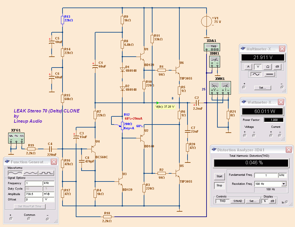
I setup Leak Stereo 70 for sim.
Think I got most of it right.
I changed transistors, used
- BC560C for input
- BD139, BD140 (TO126) to replace those TO39
- Used 2N3055A and then later TIP3055 for output
TIP3055 did lower distortion quite a bit, compared to 2N3055A
First there was something wrong. Did not work.
I had forgot to put in the 470p compensation cap at the input BC560C.
After this everything went well.
I must say I was really surprised to see how good amplifier it is.
Considering so few transistors it is really great!
THD
0.003 % at 1 Watt 8 Ohm
0.012 % at 10 Watt
0.046 % at 60 Watt
Amplifier is called LEAK Stereo 70, but I could not get 70 Watt with reasonable distortion.
But 60 Watt with low dist is not bad.
The blue components in schema are for adjust.
If you do not get the recommended 37 Volt at output node,
then I suggest you do like me. Change the value of R13 in upper left.
The idle DC Current in output is set 30 mA, as recommended.
What I really would change, is the GAIN.
As you can see it takes only ~0.500 Vrms to get close to max output.
So by changing R18 at the bottom, from 2.2k to 1k (or 1.2k)
we get a normal modern Gain level.
(It is not unusual old amplifiers have much more gain, as the level from the sources were different, lower at that time)
Attachments

What does R11 do ?
I simmed the circuit you have shown using Beigebag and I get the second harmonic as 0.043% at about 1 watt into 8 ohms. That's close to what I measured on a similar circuit I tried out.
The sound is good in any case. But I can see harmonics ( measured ) all the way out to 20 Khz ( about -80dbV or so) on a 1 Khz test signal !
What THD we get, of course, depends on what transistor models we use.
But such big difference is not expected.
Beigebag is a very good sim, what I know. I use MultiSim.
TIP3055 I have downloaded from somewhere. 2N3055A was in MultiSim library.
BD139 BD140 are from Philips website NXP Semiconductors
BC560C I have downloaded.
If your sim is close to reality, you can be happy.
R11 mystery.
I can not tell. We could measure currents.
Because it does balance currents in some way.
R11 puts 2mA extra across R3.
This means we need 2 mA less in U2 BD140.
One thing we could do is to run with and without R11, and observe any difference.
Yeah , you are right about the variation in models causing different results.
Beigbag seemed to have these on their list but the 2N3055 would not appear in the npn power transistor list. I could see it only if ALL npn transistors were selected. Strange. Maybe it isn't a good model after all.
I missed clarifying the fact that the circuit I tried was NOT the exact circuit as you have tried and that could possibly be another cause of ( measured) differences. However it's quite interesting to check it out.
I'll try the R11 sim and see what it does. Might indicate why they put it there.
Cheers.
FYI this amp is rated 35W per channel. The 70 bit refers to the output of both channels. They suffer from high order crossover products due to the asymmetrical quasi complementary output stage without Baxandall diodes.
I have owned around six of these over the years and do like them as a period piece and bit of industrial design but I can't say that they sound good..... good for a solid state amp in the late sixties maybe but rather veiled and mushy by modern standards.... and gets harsh as the volume is pushed up.
The Delta 70 is basically the same design but was the version made by The Rank Organisation after they had bought out Leak (they were then made in Idle, Bradford as part of the Wharfedale operation AFAIK). The Delta version is re-styled and rather more robust due to larger heatsinks and a few other detail changes.
Dear Sherloq,
I would get a new one Leak 70 or some thing a little better and renovate the working one with new capacitors, for a slightly more modern and simpler project I would and have renovated Quad 303's the price is higher at about 100 Pounds on Uk ebay and less for a broken one. Get an old sugden a21 if you can. Also when it comes to renovating an amp its nice to have a working one to compare voltages on the schematic.
Good luck what ever you plan to do.
If you do renovate any old amplifier that is working replace all the electrolytic capacitors. Replacing nearly all the capacitors will likely cost around 60 -90 Euro's for a 1970's amplifier. If its not working find new equivalents for all the transistors (buy some extra transistors especially for the output stage (as you may blow up the transistors while your doing the job. 95% of the time what is broken is the output transistors irrespective of make for 1970's amplifiers.
I could get the sim to work with the compensation cap across the VAS but in practice that didn't work. The bottom half of the sine wave would burst into oscillation , just enough to thicken it very noticeably on the scope. But using a comp cap across the base collector of the input transistor ( as in the original circuit ) completely cured the problem. No comp cap on the VAS. I will need to use ARTA to check out the distortion as my hardware set up can only show about 0.01%. But the FFT shows harmonics all the way up to 20 Khz. Haven't listened to it yet to see how it sounds after all the tweaking.
I could get the sim to work with the compensation cap across the VAS but in practice that didn't work. The bottom half of the sine wave would burst into oscillation , just enough to thicken it very noticeably on the scope. But using a comp cap across the base collector of the input transistor ( as in the original circuit ) completely cured the problem. No comp cap on the VAS. I will need to use ARTA to check out the distortion as my hardware set up can only show about 0.01%. But the FFT shows harmonics all the way up to 20 Khz. Haven't listened to it yet to see how it sounds after all the tweaking.
R11 in post 5 appears to help overload recovery .
Clip the output severely with and without the resistor and you will see the difference. Have not yet thought about the mechanism that is involved in the improvement.
Cheers.
1. You have noticed harmonics in FFT.
If there is a weakness in this amplifier, it is the frequency, AC characteristics.
Remarkably few transistor, considering this very good amplifier.
But making things extremely simple should have a cost.
And the AC curve is one such thing.
Maybe there is some tweaking to improve this?
2. R11 in post #5.
Maybe you are right. Can be to improve clipping behavior.
3. Comp cap at input.
It is there it does the best.
In this amplifier.
Of course we can try different values.
Compare the input and feedback of Leak Stereo 70 and DOZ, Death of Zen.
It is is the same idea.
DOZ is a Class A and has got no compensation.
An externally hosted image should be here but it was not working when we last tested it.
I tried this type of circuit with typical resistor load and bootstrap capacitor and another with CCS load on the VAS. The bootstrapped version appears to be better !
Nothing new of course. Hugh and many others have have said that the bootstrapped version sounds better in some of their amps.
Mild clipping appears to be acceptable though there is some recovery problem when coming out of the clipped condition. Bad clipping is terrible. Haven't tried the resistor in a real world amp. My post about R11 helping recovery was SIM based.
But then I blew some power transistors !
So more work will have to wait. Too many other non audio things have to be done !
I had said that the Leak Delta70 which I heard in the late 70's was very good.
Having tried out a reasonably similar circuit now , I am convinced that it "must" have been good. Might be worthwhile fixing an old unit and taking care to change all suspect components especially the capacitors.
Not as good as modern equipment ? It might give you surprising results !
Have fun.
Having tried out a reasonably similar circuit now , I am convinced that it "must" have been good. Might be worthwhile fixing an old unit and taking care to change all suspect components especially the capacitors.
Not as good as modern equipment ? It might give you surprising results !
Have fun.
april update
I want to update what I said earlier. I find the 'fairly' identical copy of the Delta70 a very musical sounding amp. Nice and punchy too. No doubt there will be slightly better sounding amps especially as the input cap contributes a lot to the sound of the amp. But it is a good amp.
As soon as I settle down in my 'new' apartment, I will try out some variations on the basic design. Might take several weeks !
Hello Sherloq,
I second "Jez" about the output stage of the Leak Delta 70 circuit. This particular amplifier was noted by Linsley Hood in his book "Valve & Transistor Audio Amplifiers" pp.145-150 as an example of 1960's design. This book is highly worth reading.
At that time quasi complementary output stage halves (Q/C) were significantly asymmetrical. The transfer slope of each output half was different as was the optimum bias current. Distortion effects were more prominent at normal listening levels than at full power - quite the reverse of the classic Leak valve amplifiers of yore.
A Q/C enhancement by I.M. Shaw in 1969 involved inserting a forward biased diode between the collector of the lower NPN power transistor and associated ballast resistor -ensuring an equivalence of diode junctions in each output half. Baxandall's circuit does this in a better way - but that would be a little more difficult to adapt to the Leak 70 cicuit board as it would involve cutting a couple of traces and drilling new holes.
This diode equivalence principle is used in the Quad 303 triple output circuit and technically that design is a better example of a classic amplifier. "Owenhamburg" is on the money with his choice and general approach there.
Applying the Shaw modification to the Leak would be simple enough for someone with experience - unsolder the lower end the ballast resistor between output and the lower power transistor and stand it up so the top end could be soldered to a 3 amp diode connected to the hole vacated by the other end. The presence of the extra diode will affect biasing and some changes to resistor values will be necessary. I use hands on rather than simulations but someone might care to model the modification for you and suggest the changes in values.
Member
Joined 2009
Paid Member
That's what I call optimism - posting a reply to a question raised 1 and half year ago !
By the way, I also like this design, one of the few schematics I keep on file. My TGM3 shares a lot of the first half of this amp.
Interesting about the Shaw solution, I never heard of this one before.
By the way, I also like this design, one of the few schematics I keep on file. My TGM3 shares a lot of the first half of this amp.
Interesting about the Shaw solution, I never heard of this one before.
Hello Bigun,
Shaw's modification was published in Wireless World June 1969 pp. 265-266. Shortly after that Baxandall wrote in Wireless World - September 1969 pp. 416-417 proposing a more elegant way of achieving the same result and that had immediate appeal to contemporary designers.
This left little time to incorporate Shaw's ideas into commercial product and he is less well known for his contribution.
I respect that an owner might keep his amplifier as original as possible and enjoy it that way - I have a Hi-Fi collector acquaintance who owns a Delta 70 and regards it as a piece of history.
This item of kit is not expensive to acquire and interest in experimenting with/restoring the equipment seems an equally valid consideration for enthusiasts - some of whom might want to improve the performance.
I mentioned the Shaw modification, and references, with that in mind as it would give an understanding of the technical issues, be simple to implement (and easy to restore one's circuit board to original).
The Baxandall Q/C circuit was a major advance at the time and is still preferred by some Hi-Fi manufacturers over full complementary symmetry output arrangements.
Please read the references quoted. The arguments are balanced and well laid out
- Status
- This old topic is closed. If you want to reopen this topic, contact a moderator using the "Report Post" button.
- Home
- Amplifiers
- Solid State
- Leak Delta 70 - Attempt DIY, Overhaul or buy another amp?