And now, it's rebaptised: it's....
....The CIRCLOFLOP!!!
However, it does have some unusual features: it is capable of directly driving unwieldy loads, such as high Q, undamped parallel or series resonant circuits, as well as pure reactive loads, at high power and high frequencies.
Look Mum, no Zobel...!....!.:
....The CIRCLOFLOP!!!
However, it does have some unusual features: it is capable of directly driving unwieldy loads, such as high Q, undamped parallel or series resonant circuits, as well as pure reactive loads, at high power and high frequencies.
Look Mum, no Zobel...!....!.:
Attachments
-
 79303d1243853369-tuto-projet-amplificateurs-n-vdmos-de-lefficace-rationnel-serieux-resfluo11.jpg47.6 KB · Views: 5,165
 -
 79757d1244283952-tuto-projet-amplificateurs-n-vdmos-de-lefficace-rationnel-serieux-circloparres1.jpg194 KB · Views: 4,544
 -
 79758d1244284251-tuto-projet-amplificateurs-n-vdmos-de-lefficace-rationnel-serieux-circloparres2.jpg301.5 KB · Views: 4,190
The Circloflop isn't dead yet...
....just on life support.
Here are some more pics:
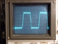
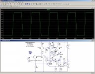
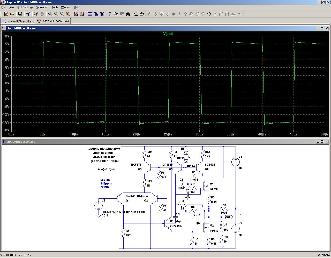
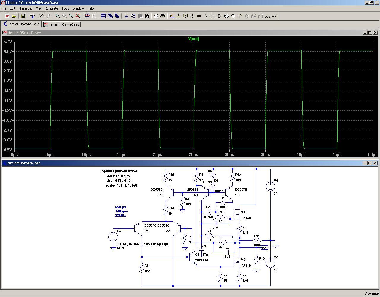
First the simulated response to a 100KHz square wave, on a pure capacitive 100nF load.
Second, the same, but in the real world (capacitor is Siemens polypropylene B32650, 0.1µ/400V)
....just on life support.
Here are some more pics:
First the simulated response to a 100KHz square wave, on a pure capacitive 100nF load.
Second, the same, but in the real world (capacitor is Siemens polypropylene B32650, 0.1µ/400V)
Attachments
Last edited:
Their simulations are without the capacitor coupling (C1).
What the function of R11? not missing this one capacitor!
What the function of R11? not missing this one capacitor!
C1 is in circuit, and it is the main compensation capacitor (not coupling).
R11 is the output load; its value varies (from 1ohm to 10 megohm) according to the type of test performed.
R11 is the output load; its value varies (from 1ohm to 10 megohm) according to the type of test performed.
OK, I'll bite - what's it for then, if "not intended for audio"?
Is it running in class A or B? - I haven't simmed it but the circuit looks like it could do either. Presumably something somewhere is adjustable to set the bias?
Nice to see something different / original 🙂
Is it running in class A or B? - I haven't simmed it but the circuit looks like it could do either. Presumably something somewhere is adjustable to set the bias?
Nice to see something different / original 🙂
It is a "lab workhorse", an all-purpose power amplifier, designed to drive all sorts of transducers (including loudspeakers), transformer, coils, etc, at various frequencies, from DC to ultrasonic. It also does stress-testing of components or subassemblies, to simulate load-dumping conditions f.e., or inject interferferences into power supply lines.OK, I'll bite - what's it for then, if "not intended for audio"?
This is why it has to be extremely stable, robust and tolerant, without any network in the output which might degrade the accuracy.
And it has to cheap, in case things go really wrong.
It operates in AB, under near-square law conditions (insofar as the transfer function of the FETs permits). The Iq is about 120mA, with a strong negative coefficient (in the sim at least: with real components, heatsinks and non-ideal thermal couplings, things are more even).Is it running in class A or B? - I haven't simmed it but the circuit looks like it could do either. Presumably something somewhere is adjustable to set the bias?
The bias could be made adjustable by making part of R12 variable, but I used no trimmers, and selected D2 instead.
D5 compensates for Q3 Q5 Q6, and D6 for the output transistors.
Thanks for the appreciationNice to see something different / original 🙂
Attachments
Some further details:
First, more stress-tests.
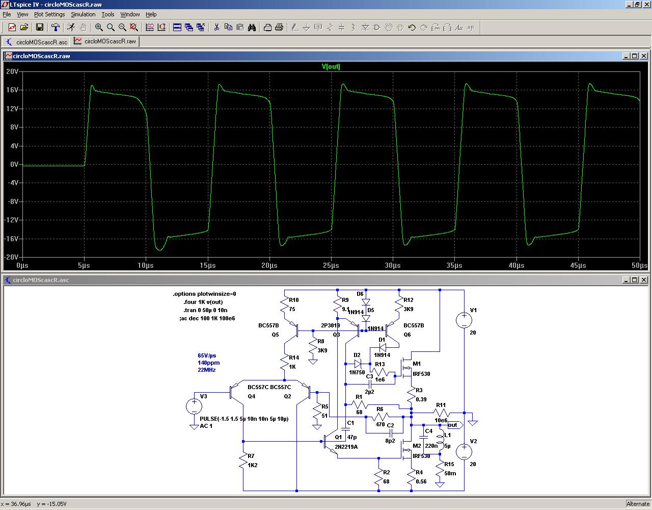
On a (quasi) pure inductive load of 10µH:
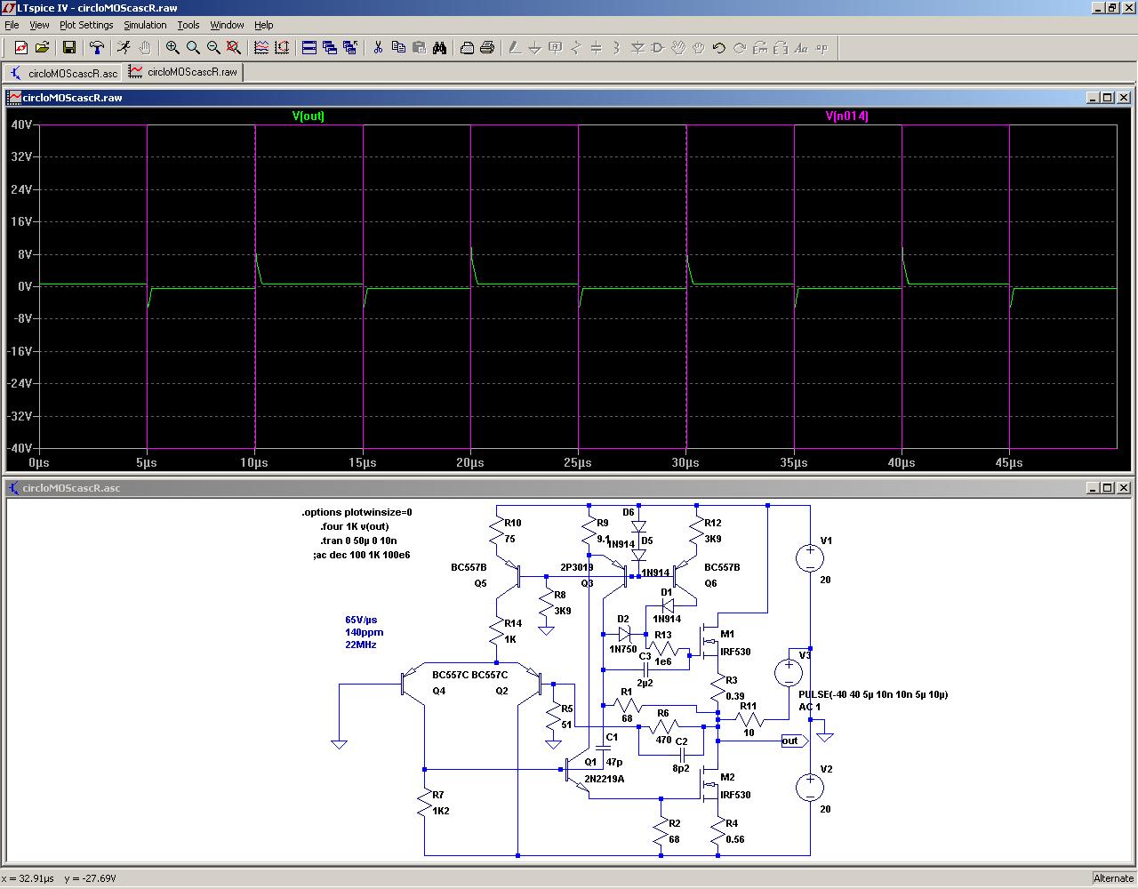
The load dumping condition: the load forces an 80Vpp, 100KHz square wave (magenta) into the output of the amplifier (green). That's twice the supply voltage of the amplifier:
Now, a low impedance test, with a 1ohm load (for obvious reasons, the voltage is limited to 9Vpp):
Next, the load is a high-Q parallel resonant circuit:
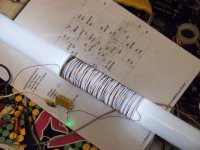
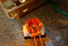
Here is a real-life application of the above simulation: inductive heating of a screw. First, the test set-up:
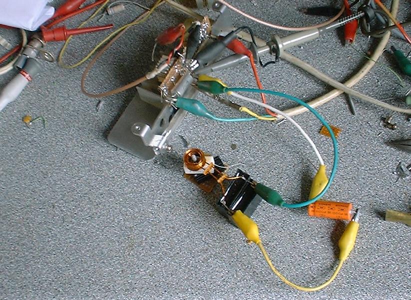
And then the thing in action:
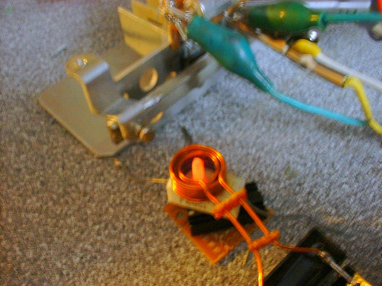
(Sorry for the pic quality, the coil was beginning to catch fire)
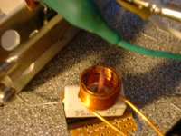
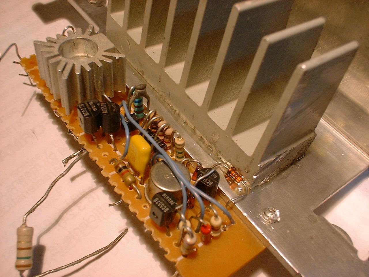
A close-up of the prototype, showing the heading of the thread is properly chosen:
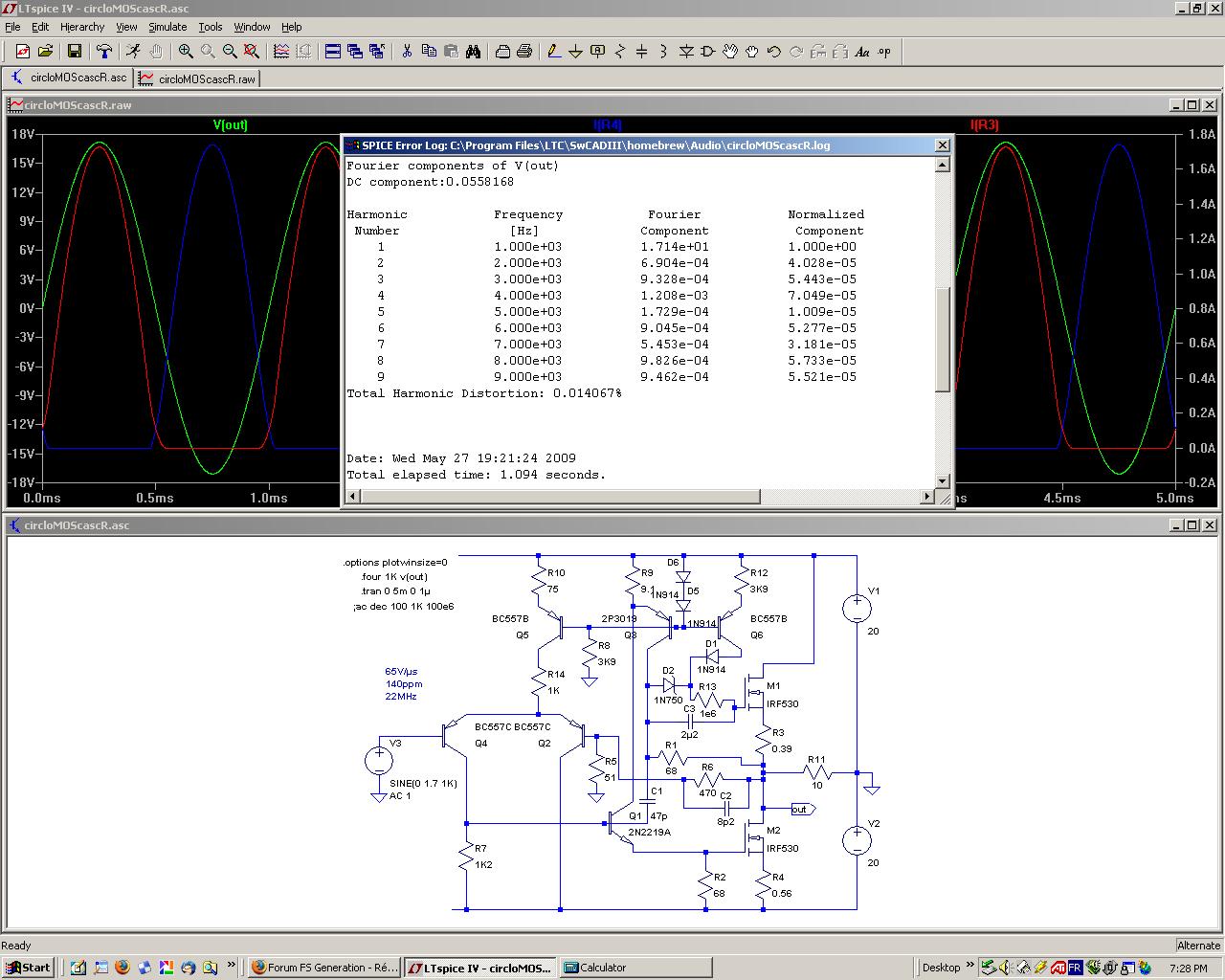
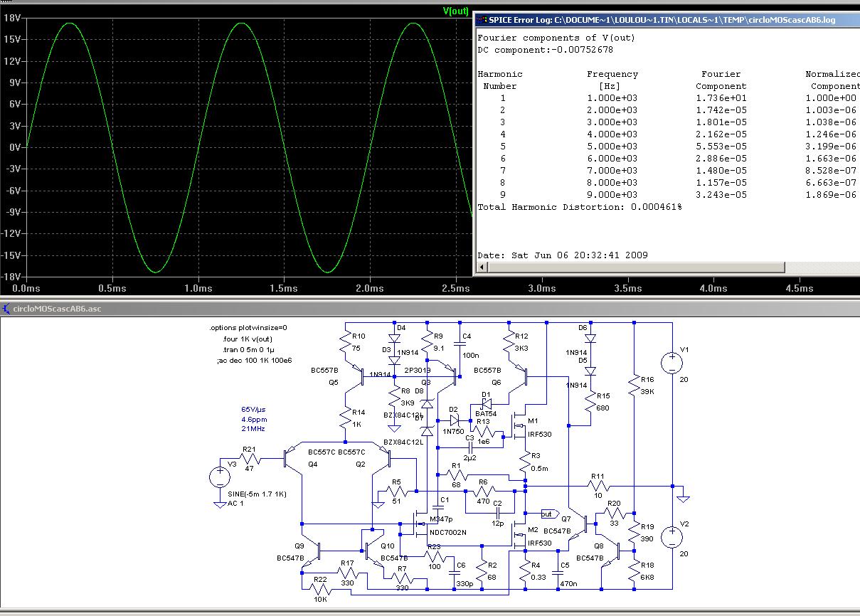
Finally, a more serious note: a look at the distortion:
First, more stress-tests.
On a (quasi) pure inductive load of 10µH:
The load dumping condition: the load forces an 80Vpp, 100KHz square wave (magenta) into the output of the amplifier (green). That's twice the supply voltage of the amplifier:
Now, a low impedance test, with a 1ohm load (for obvious reasons, the voltage is limited to 9Vpp):
Next, the load is a high-Q parallel resonant circuit:
Here is a real-life application of the above simulation: inductive heating of a screw. First, the test set-up:
And then the thing in action:
(Sorry for the pic quality, the coil was beginning to catch fire)
A close-up of the prototype, showing the heading of the thread is properly chosen:
Finally, a more serious note: a look at the distortion:
This is the first time I see an audio amplifier doing that. At what frequency/amplitude is it?inductive heating of a screw
In the case of the screw, the frequency was ~45KHz, and maximum amplitude (35Vpp).
The series resonant circuit exciting the fluorescent tube was driven at around 120KHz, also 35Vpp.
The series resonant circuit exciting the fluorescent tube was driven at around 120KHz, also 35Vpp.
Quite a beast! Seems to do what you wanted. =) I like the part about injecting noise into power lines. That would be very handy.
As good as it is on difficult loads, wonder how it would do driving electrostatic panels? Should do well.
.
As good as it is on difficult loads, wonder how it would do driving electrostatic panels? Should do well.
.
It should do well, but in this version, a transformer would still be necessary.As good as it is on difficult loads, wonder how it would do driving electrostatic panels? Should do well.
But it would also be possible to "unfold" the cascode, in order to use only high voltage/N devices in the driver and output stages. This should make a direct drive possible.
I like it
I have been looking round the net for designs that use all N channel mosfets & i have to say that this must be one of the most innovative that i have seen 😉
I just love the way it can swing nearly rail to rail by the simple addition of a capacitor (2.2uf), as you know you'd normally need a higher supply voltage on the positive side.
I take my hat off to you Elvee
Any idea on the damping factor? I should imagine it should be pretty high or certainly could be made to be so. With no output inductor it should it should be fairly high to high frequencies to.
Very interesting, you have gotten me thinking 😀
Congratulations, event horizon, you were smart enough to catch the main innovation of the design!I just love the way it can swing nearly rail to rail by the simple addition of a capacitor (2.2uf), as you know you'd normally need a higher supply voltage on the positive side.
This version has an output impedance of ~100millohm.Any idea on the damping factor? I should imagine it should be pretty high or certainly could be made to be so. With no output inductor it should it should be fairly high to high frequencies to.
At relatively low frequencies at least; at higher frequencies, you can have an idea of the behaviour by looking at the load-dumping and low-impedance tests.
But as you rightly conjecture, it is indeed possible to improve this factor, and I will also describe a more elaborate version doing about 20dB better on this point.
Next variant is equipped with an auto-bias servo circuit.
This inclusion is easy and natural, thanks to the already present threshold shifter.
Most of the circuit and characteristics remain unchanged, one of the source resistors can be eliminated.
Iq is set by the ratio of R18 to R19.
This inclusion is easy and natural, thanks to the already present threshold shifter.
Most of the circuit and characteristics remain unchanged, one of the source resistors can be eliminated.
Iq is set by the ratio of R18 to R19.
Attachments
This is a very interesting design, and I really liked the picture of the glowing screw sitting... umm, err, sitting a couple of cm above a very flammable carpet..  Could have been quite exciting 😱 Ought to exercise a little more caution... 😛
Could you please post a full size schematic from the sym as the ones presented do not render properly on any of several PCs I have access to. (Windows & Linux)
I'm thinking this design would be near ideal for use as the PA in an active AC line conditioner/source using a toroid as a step up transformer. Target power would be a couple of hundred watts at 60Hz.. The fact that this thing appears to be indestructible makes it ideal for driving all manner of loads reflected back through the output transformer.
You might want to consider offering a PCB for this design as I suspect (naively hope) that there would be some interest here?
Could have been quite exciting 😱 Ought to exercise a little more caution... 😛Could you please post a full size schematic from the sym as the ones presented do not render properly on any of several PCs I have access to. (Windows & Linux)
I'm thinking this design would be near ideal for use as the PA in an active AC line conditioner/source using a toroid as a step up transformer. Target power would be a couple of hundred watts at 60Hz.. The fact that this thing appears to be indestructible makes it ideal for driving all manner of loads reflected back through the output transformer.
You might want to consider offering a PCB for this design as I suspect (naively hope) that there would be some interest here?
Last edited:
Don't worry: it's a melamine coated MDF board. No risk.This is a very interesting design, and I really liked the picture of the glowing screw sitting... umm, err, sitting a couple of cm above a very flammable carpet..
I'll try.Could you please post a full size schematic from the sym as the ones presented do not render properly on any of several PCs I have access to. (Windows & Linux)
A word of caution: robust is not synonymous with indestructible, and if you grossly exceed the dissipation or SOA limits of the output devices, you will fry them (it happened to me).I'm thinking this design would be near ideal for use as the PA in an active AC line conditioner/source using a toroid as a step up transformer. Target power would be a couple of hundred watts at 60Hz.. The fact that this thing appears to be indestructible makes it ideal for driving all manner of loads reflected back through the output transformer.
But it is true that this amplifier is capable of driving loads that nobody in his right mind would dare putting even close to the output terminals of a "normal" amplifier. And it drives them with insane signals, at high power and high frequency.
Also note that the input current is large, and the input impedance is low, compared to a regular audio amplifier. In 50 ohm systems, this is no problem.
And for 200W, you'd need to parallel a number of devices.
I will also describe a number of variants, including one with a special protection circuit
Sorry, I don't do PCBsYou might want to consider offering a PCB for this design as I suspect (naively hope) that there would be some interest here?
Attachments
Lower distortion
The next variant has a higher loop gain.
This results in a higher feedback factor, and a reduced distortion: the linearity is now around 5 ppm at near-full power (0.0005% dist.)
Other characteristics remain practically unchanged.
The next variant has a higher loop gain.
This results in a higher feedback factor, and a reduced distortion: the linearity is now around 5 ppm at near-full power (0.0005% dist.)
Other characteristics remain practically unchanged.
a bit of ....off topic
is there anyone that can answer me a question regarding induction heating as seen in the example of the OP ????? please ????
the question is:
if a circuit like that consuming so litle power can make a screw actually glow why is there no one so far designed some device that has 4-5 similar coils and 4-5 similar screw or other metal parts, that your home water supply runs through this device cold at the input and boiling hot at the output ?????
i have seen various applications on the internet but nothing like that ...
is there any darwbacks ???? or something i ve missed ???
- Status
- Not open for further replies.
- Home
- Amplifiers
- Solid State
- It's cheap, it's N, it's dirty, it's.... The CIRCLOMOS!!!