Hi AKSA,Very impressive work, Elvee, thank you! Can you do something with 50V rails?
Hugh
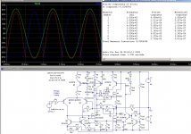
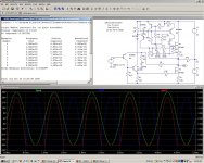
I did all of the simulation at 20V, and most of the physical work at between 15 and 25V, approximately. Upgrading it to 50V shouldnt pose major difficulties, and I just made a quick test on the sim: I changed the 20V supplies to 50V ones, and nothing else (except the input level). As you can see, the result is rather encouraging: the linearity has degraded by just 2ppm, mainly second harmonic, probably caused by the onset of an asymetrical clipping.
The quiescent current has increased to ~300mA, which is too much obviously, but these are rather minor issues.
Of course, in the real world, the transistors would have to be upgraded to more powerful, 120V or 150V types, but this normal.
I will think about it, anyway.
The comment of Panomaniac also sparked me into thinking of a full-N, high voltage (+/-700V) version:
It should do well, but in this version, a transformer would still be necessary.Originally Posted by panomaniac
As good as it is on difficult loads, wonder how it would do driving electrostatic panels? Should do well.
But it would also be possible to "unfold" the cascode, in order to use only high voltage/N devices in the driver and output stages. This should make a direct drive possible.
I think I'll be able to come up with something viable.
Attachments
is there anyone that can answer me a question regarding induction heating as seen in the example of the OP ????? please ????
the question is:
if a circuit like that consuming so litle power can make a screw actually glow why is there no one so far designed some device that has 4-5 similar coils and 4-5 similar screw or other metal parts, that your home water supply runs through this device cold at the input and boiling hot at the output ?????
i have seen various applications on the internet but nothing like that ...
is there any darwbacks ???? or something i ve missed ???
What makes you think the circuit was "consuming so little power" while doing that?
In fact, the amplifier was run at full power, and everything went hot like hell in a matter of seconds: the heatsink, the resonance capacitors, and the coil, whose enamel caught fire almost immediately.
Inductive heating is not new, but in general, a special power driver is required:
Google Image Result for http://www.inductionatmospheres.com/jpg/fusing_top.jpg
And the coil is normally water-cooled.
But achieving a similar result with a general-purpose, low distortion amplifier is a bit unusual.
Don't try this with your favorite amplifier....
How sensitive is the amp to different parts?
I would like to build this amp, but i dont have the different transistors.
Can i build the same circuit but with BC556B/BC546B and IRFP250?? This is what i have at home at the moment.
This looks like it would make a very stable and powerful subwoofer-amp.
Something with 80 volt rails and 20 IRFP250 on the output?!
Hi Elvee
When you increase loop gain to reduce distortion, doesn't that hurt the stability margin? I remember thinking, when I saw your first circuit that it's stability into obscene loads was probably largely due to few gain stages and relatively low loop gain.
I would have thought that for heating screws, injecting noise into power lines etc, bullet-proof stability would be more important than ultra-low distortion? Or has this circuit gotten a wee bit side-tracked from strictly work-related uses?")
On an unrelated note: what's with the 10k resistor connected to the emitter of Q9? Looks like it gives some semi-local positive feedback, but only when M2 is conducting.
Cheers - Godfrey
When you increase loop gain to reduce distortion, doesn't that hurt the stability margin? I remember thinking, when I saw your first circuit that it's stability into obscene loads was probably largely due to few gain stages and relatively low loop gain.
I would have thought that for heating screws, injecting noise into power lines etc, bullet-proof stability would be more important than ultra-low distortion? Or has this circuit gotten a wee bit side-tracked from strictly work-related uses?
On an unrelated note: what's with the 10k resistor connected to the emitter of Q9? Looks like it gives some semi-local positive feedback, but only when M2 is conducting.
Cheers - Godfrey
How sensitive is the amp to different parts?
I would like to build this amp, but i dont have the different transistors.
Can i build the same circuit but with BC556B/BC546B and IRFP250?? This is what i have at home at the moment.
This looks like it would make a very stable and powerful subwoofer-amp.
Something with 80 volt rails and 20 IRFP250 on the output?!
In general, it is pretty tolerant to most parts variations, but you have to be more careful with the components defining the quiescent current, especially for the simpler, non-servoed version. They include the threshold shifter reference D2, and the PNP VAS Q3: a larger area transistor will generate a higher common circlo bias current, hence a higher Iq.
In some sim versions Q3 is a 2N2905, and other use a "synthetic" PNP version of the 2N3019, and there are minor adaptations to accomodate differences. Physical versions use mostly the 2N2905.
The voltage of D2 and the common circlo bias current have to harmonize with the threshold voltage of your MOS transistors; some recalculations, simulations and tests will probably be necessary for optimum results with widely different devices.
BC546/556 are OK.
The 80V rails shouldn't be a problem, but if you build a "big" version of this amplifier, it is probably a good idea to have a less primitive reference for the current sources than D3/D4: either some conventional CCSs, or something like Q8 in the AB6 version will be more stable wrt supply variations.
Paralleling a large number of output devices would probably require a modification to the frequency compensation, due to the much larger input capacitance.
There too, I recommend you make some simulations and tests.
Also note that this amplifier has a wide bandwidth, and you cannot afford a sloppy PCB design. Another possibility is to "clip its wings", i.e. include generous gate stoppers, increase the frequency compensation, etc.
Thanks for all the good info. I think this is a very clever way to use only N-fets in a pushpullamp. Very simple but clever.
I have been drawing variations of your amp for a couple of hours now, and i realy like it. (drawing variations is my why of learning about and working out what everything does in the circuit)
I only have BD139 and BD140 as possible replacements for Q1 and Q3.
I think i will have to try... Some magic smoke is a great way to learn.
Hi Godfrey,Hi Elvee
When you increase loop gain to reduce distortion, doesn't that hurt the stability margin? I remember thinking, when I saw your first circuit that it's stability into obscene loads was probably largely due to few gain stages and relatively low loop gain.
I would have thought that for heating screws, injecting noise into power lines etc, bullet-proof stability would be more important than ultra-low distortion? Or has this circuit gotten a wee bit side-tracked from strictly work-related uses?
On an unrelated note: what's with the 10k resistor connected to the emitter of Q9? Looks like it gives some semi-local positive feedback, but only when M2 is conducting.
Cheers - Godfrey
The higher gain version may not be as bullet-proof as the simple one, but it still does a decent job.
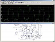
Here is an example, only slightly different from the AB6: it uses a bjt as a driver, and is shown driving a 470nF capacitor directly.
The schematic is a bit fuzzy, because parasitics are included.
As you can see, it it is relatively well-behaved (OK, not perfect, but it is a 100KHz square wave).
This test has been made for real, and the result is quite similar, but the amplifier blows after seconds, due to excessive dissipation in the MOS, not instability.
This version uses a nested compensation which improves stability.
And BTW, heating screws was not included in the original requirements: the idea came along the way.
The 10K resistor compensates for the slight asymetry caused by the current-sensing resistor R4, and it lifts the gain when M2 is conducting, restoring the symetry.
It also compensates for the unbalanced zero-signal circlo driver current, made necessary by the threshold shifting circuitry.
Attachments
What makes you think the circuit was "consuming so little power" while doing that?
In fact, the amplifier was run at full power, and everything went hot like hell in a matter of seconds: the heatsink, the resonance capacitors, and the coil, whose enamel caught fire almost immediately.
Inductive heating is not new, but in general, a special power driver is required:
Google Image Result for http://www.inductionatmospheres.com/jpg/fusing_top.jpg
And the coil is normally water-cooled.
But achieving a similar result with a general-purpose, low distortion amplifier is a bit unusual.
Don't try this with your favorite amplifier....
WELL ....actually i did try that with a pro amplifier but due to the normal reasons i only used a 10 khz frequency on any available crossover coil and i did managed to make a screw warm .... so it is working ....
i ve seen on the internet huge bolts glowing powered from a 9 v battery ...efeciency is there with this topology ...still i dont know why not in a home appliannce
"...still i dont know why not in a home appliannce"
Doesn't induction stove count?
Very efficient and fast. The drawback is that the pot needs to be ferrous.
Iron is nice here.
Back on topic.
Why did Circlomanen have to link this, now I'm interested too =)
Adapted to IRF240 (TO3) perhaps...
Doesn't induction stove count?
Very efficient and fast. The drawback is that the pot needs to be ferrous.
Iron is nice here.
Back on topic.
Why did Circlomanen have to link this, now I'm interested too =)
Adapted to IRF240 (TO3) perhaps...
Back on topic.
Why did Circlomanen have to link this, now I'm interested too =)
Because im evil!!!!
No, this is a very intriging amp. I have dug out all the stuff from my attic.
I have a lots of IRFP260 and one IRFP250. I guess i have to try the IRFP260.
All i need to buy is some zeners and some 1 ohm power-resistors.
Is the amp sensitive to noise from the powersupply???
Im going to try some gatestoppers. 100 ohms or so. I hope that will be a little more forgiving to my layout and the stability. I dont need full power clean squarewave at 100 kHz. Maybe a single transistor input. I dont like LTPs very much. They are usualy not very stable.
Going audio
Here are some recommendations for those wanting to build an audio version of this amplifier.
As I said at the beginning of this thread, it was not initially intended for audio applications.
The main points requiring adaptation are:
-Input impedance (too low)/input current (too high)
-Frequency response extends to DC
-Bandwidth is too large
I will provide some hints at solving these problems. Remember however that unexpected problems might always appear if you carry out modifications. The original circuit works as advertised, but I cannot give a similar guarantee on circuits that have not been tried and tested.
I recommend you begin with the original design, and make incremental changes, to get the feel on how the circuit behaves. A prototype can be built for peanuts, as can be seen from the picture.
Or you start from scratch, and you redesign a purely audio amplifier based on the same basic principles.
The input impedance issue could be solved by using composites in the input LTP: see CircloBuf.
This has not been physically tested, just simulated.
Cutting the DC response can be achieved by the traditional solution of placing a (large) capacitor in series with R5. Alternatively, a coupling capacitor could be used in the input, but some form of offset adjustment would probably be required (unless monolithic pairs are used for Q2/4 and Q7/8).
The bandwidth problem is more difficult: I have just tried to make a simulation including gate stoppers, but this has the effect of degrading the stability margin to dangerous levels.
A more serious redesign would be required to cleanly limit the bandwidth.
I therefore recommend to limit the frequency at the input, using a small RC low-pass.
This means the PCB layout around the output transistors has to be clean and short.
Anyway, this version is a bit more limited already, with only 8MHz of small-signal bandwidth.
A better reference for the current sources would help.
Or R8 could be split and returned to V-, with a decoupling capacitor to V+ at the common.
A thing of interest is the clipping behaviour. It is pretty neat as you can see from CircloClip.
Finally, for those wanting to experiment by themselves, here is the LTspice file (change the .txt into .asc):
Here are some recommendations for those wanting to build an audio version of this amplifier.
As I said at the beginning of this thread, it was not initially intended for audio applications.
The main points requiring adaptation are:
-Input impedance (too low)/input current (too high)
-Frequency response extends to DC
-Bandwidth is too large
I will provide some hints at solving these problems. Remember however that unexpected problems might always appear if you carry out modifications. The original circuit works as advertised, but I cannot give a similar guarantee on circuits that have not been tried and tested.
I recommend you begin with the original design, and make incremental changes, to get the feel on how the circuit behaves. A prototype can be built for peanuts, as can be seen from the picture.
Or you start from scratch, and you redesign a purely audio amplifier based on the same basic principles.
The input impedance issue could be solved by using composites in the input LTP: see CircloBuf.
This has not been physically tested, just simulated.
Cutting the DC response can be achieved by the traditional solution of placing a (large) capacitor in series with R5. Alternatively, a coupling capacitor could be used in the input, but some form of offset adjustment would probably be required (unless monolithic pairs are used for Q2/4 and Q7/8).
The bandwidth problem is more difficult: I have just tried to make a simulation including gate stoppers, but this has the effect of degrading the stability margin to dangerous levels.
A more serious redesign would be required to cleanly limit the bandwidth.
I therefore recommend to limit the frequency at the input, using a small RC low-pass.
This means the PCB layout around the output transistors has to be clean and short.
Anyway, this version is a bit more limited already, with only 8MHz of small-signal bandwidth.
Yes, it does have some sensitivity from the positive rail, mainly.Is the amp sensitive to noise from the powersupply???
A better reference for the current sources would help.
Or R8 could be split and returned to V-, with a decoupling capacitor to V+ at the common.
A thing of interest is the clipping behaviour. It is pretty neat as you can see from CircloClip.
Finally, for those wanting to experiment by themselves, here is the LTspice file (change the .txt into .asc):
Attachments
An externally hosted image should be here but it was not working when we last tested it.
This is what i want to build. I dont know how to sim this amp, but i will try to learn LT-Spice in the near future..
Its only a rough first take on this amp. I have not included any stabilizing stuff at all.
The input impedance issue could be solved by using composites in the input LTP
Could i use a darlington (BD679) or a ND2540 FET as VAS/Phasesplitter????
That should make it possible to use less current through the inputstage?
It is a "lab workhorse", an all-purpose power amplifier, designed to drive all sorts of transducers (including loudspeakers), transformer, coils, etc, at various frequencies, from DC to ultrasonic. It also does stress-testing of components or subassemblies, to simulate load-dumping conditions f.e., or inject interferferences into power supply lines.
This is why it has to be extremely stable, robust and tolerant, without any network in the output which might degrade the accuracy.
And it has to cheap, in case things go really wrong.
It operates in AB, under near-square law conditions (insofar as the transfer function of the FETs permits). The Iq is about 120mA, with a strong negative coefficient (in the sim at least: with real components, heatsinks and non-ideal thermal couplings, things are more even).
The bias could be made adjustable by making part of R12 variable, but I used no trimmers, and selected D2 instead.
D5 compensates for Q3 Q5 Q6, and D6 for the output transistors.
Thanks for the appreciation

I would be very interested in opinions on this circuit by Mr. Nelson Pass and Mr Alex Nikitin (X-pro)
And I would this topology filed there:
http://www.diyaudio.com/forums/soli...better-audio-non-complements-audio-power.html
But one Question: value of R13: 1e6.
What means this ?
Last edited:
An externally hosted image should be here but it was not working when we last tested it.
This is what i want to build. I dont know how to sim this amp, but i will try to learn LT-Spice in the near future..
Its only a rough first take on this amp. I have not included any stabilizing stuff at all.
Could i use a darlington (BD679) or a ND2540 FET as VAS/Phasesplitter????
That should make it possible to use less current through the inputstage?
Here is more or less what you want to achieve. It is simulated with symmetrical supplies to avoid DC conditions settling time issues, but it is single-supply-ready, you just have to include the input biasing divider.
Performances are not bad, considering the simplicity of the circuit.
Compensation might not be necessary, due the OL gain degeneration caused by R5. I didn't investigate this aspect.
I also include the LTspice file, it is a good starting point and a good opportunity if you want to initiate yourself to LTspice.
You will have to plug in the exact models of the devices you want to use, and make minor corrections to accommodate for different thresholds, etc. A good exercise. Good luck.
It is 1 megohm, in LTspice talk.But one Question: value of R13: 1e6.
What means this ?
Attachments
....The CIRCLOFLOP!!!However, it does have some unusual features: it is capable of directly driving unwieldy loads, such as high Q, undamped parallel or series resonant circuits, as well as pure reactive loads, at high power and high frequencies.
Look Mum, no Zobel...!....!.:
I would like to know about comercial (not typical audio) manufacturers of such so called "lab workhorses". Or did you design this basic topology (I haven't see this one before)?
Here now my simulation results of the CIRCLOMOS Post #1 (non inverted mode, as shown)
Please note:
output voltage (+20db): 10Vss load resistance (not complex): 8 ohms Gain: ~10 times (=20db)
the results are very very good at high idle current through the output
above 1A
Clipping behaivour is perfect without overshooting - through C3 there are rail to rail character (second PDF attachement).
In first PDF attachement there are:
1) schematic for damping factor over frequency
2) AC-Analysis (damping factor over frequency)
3) AC Analysis (normally frequency response)
4) Fourier Analysis lin 10 KHz (THD) K2: 540uV, K3: 230uV
5) Fourier Analysis log 10 KHz (THD)
6) Fourier Analysis log 100 KHz (THD)
7) Fourier Analysis lin 100 KHz (THD) K2: 1130uV K3: 390uV
8) Transient Analysis 1 MHz
9) Transient Analysis 10 MHz
10) schematic (normally frequency response)
Q1 must be an other outline (SOT-32, same as BD139) and must be thermal connected to the chassis ground (function of heatsink)
you can it compare to the results of post #15 and #17 about
http://www.diyaudio.com/forums/soli...-mk2-circuit-descr-arround-q12a-wanted-2.html
and about
http://www.diyaudio.com/forums/pass...m-results-pass-x-series-us-pat-5376899-a.html
I have also simulate the CIRCLOMOS-circuit from post # 21 (+/50V, current mirror by LTP)
THD values at 10 KHz: K2 = - 110db, K3 = - 130db K5 and higher: - 140 db
But at higher frequencies I don't get results and the clipping behaivour is worse. I don't like current mirror's and I did remove it in various commercial amplifiers.
My experience with current mirrors are follow (through large enhancing of the open loop gain in the low frequency aera):
For subwoofer applications very good
for midrange-, tweeter- and full range amplifier devices harsh sound
The solution in the circuit by post #1 about
http://www.diyaudio.com/forums/solid-state/122378-cambridge-audio-a3i-repairs-mods.html
as replacement topology for the current mirror in this circuit could be better - but I didn't tested.
Here is more or less what you want to achieve. It is simulated with symmetrical supplies to avoid DC conditions settling time issues, but it is single-supply-ready, you just have to include the input biasing divider.
Performances are not bad, considering the simplicity of the circuit.
Compensation might not be necessary, due the OL gain degeneration caused by R5. I didn't investigate this aspect.
I also include the LTspice file, it is a good starting point and a good opportunity if you want to initiate yourself to LTspice.
You will have to plug in the exact models of the devices you want to use, and make minor corrections to accommodate for different thresholds, etc. A good exercise. Good luck.
Thank you very much for taking the time to answer my questions and even simming my version of the amp!!!! I will try the circlomanen.txt file tomorrow. I have been working all weekend.
Its an intriguing amplifier. It cought my attention immidiatly when i saw it. I have been going through my stuff to find parts to build this one. (an audio version)
Thanx!
Johannes.
Last edited:
The first name that comes to mind is Amplifier Research:I would like to know about comercial (not typical audio) manufacturers of such so called "lab workhorses". Or did you design this basic topology (I haven't see this one before)?
AR - RF Microwave Instrumentation - Modular RF - Receiver Systems - AR Europe
R&S also does (or did?) some.
But this stuff is a bit too expensive to be expendable.....
This is why I designed my own brew.
If I understand correctly, your sim shows an Iq of 1.3A.Here now my simulation results of the CIRCLOMOS Post #1 (non inverted mode, as shown)
Please note:
output voltage (+20db): 10Vss load resistance (not complex): 8 ohms Gain: ~10 times (=20db)
the results are very very good at high idle current through the output
above 1A
Clipping behaivour is perfect without overshooting - through C3 there are rail to rail character (second PDF attachement).
In first PDF attachement there are:
1) schematic for damping factor over frequency
2) AC-Analysis (damping factor over frequency)
3) AC Analysis (normally frequency response)
4) Fourier Analysis lin 10 KHz (THD) K2: 540uV, K3: 230uV
5) Fourier Analysis log 10 KHz (THD)
6) Fourier Analysis log 100 KHz (THD)
7) Fourier Analysis lin 100 KHz (THD) K2: 1130uV K3: 390uV
8) Transient Analysis 1 MHz
9) Transient Analysis 10 MHz
10) schematic (normally frequency response)
Q1 must be an other outline (SOT-32, same as BD139) and must be thermal connected to the chassis ground (function of heatsink)
This way out of what I simmed/measured. But I did select the zener to get slightly more than 100mA@25°C. And the driver transistors are in TO5, but all my physical prototypes include a 24V zener in the collector of the NPN circlo phase shifter, even when it is not shown on the schematic (it changes nothing to the sim, only the real dissipation).
If I understand correctly, your sim shows an Iq of 1.3A.
This way out of what I simmed/measured. But I did select the zener to get slightly more than 100mA@25°C. And the driver transistors are in TO5, but all my physical prototypes include a 24V zener in the collector of the NPN circlo phase shifter, even when it is not shown on the schematic (it changes nothing to the sim, only the real dissipation).
You are right. In first step I still use such idle currents by the output stages. So I can better see the characteristic of the driver stages. The next step is to reduce the idle current to the mostly by MOSFETs used 100 mA. I will report the results, too, in the next time.
Independend of this, at +/-20V an idle current of 2A means 40W loss power - not too much for top quality sonic results (a medium size heat sink isn't a problem).
The 24V zener diode in the collector line is also a good idea, perhaps bypassed with a capacitor.
Last edited:
The first name that comes to mind is Amplifier Research:
AR - RF Microwave Instrumentation - Modular RF - Receiver Systems - AR Europe
R&S also does (or did?) some.
Unfortunately I find only RF amplifier devices there (lowest frequency: 10 KHz).
It would take the colloquial term of the Circlomos to find a comparable commercial product respective commercial brand about google.
Here now the second PDF attachement - same conditions than my first attachement except idle current through the output stage: now only 96mA (M1) and 133mA (M2) and much more bad THD results (as always observe by reducing the idle current):
1) schematic for damping factor over frequency
2) AC-Analysis (damping factor over frequency)
3) AC Analysis - not show !! (normally frequency response)
4) Fourier Analysis lin 10 KHz (THD)
5) Fourier Analysis log 10 KHz (THD)
6) Fourier Analysis log 100 KHz (THD)
7) Fourier Analysis lin 100 KHz (THD)
8) Transient Analysis 1 MHz
9) Transient Analysis 10 MHz
10) schematic (normally frequency response)
And now the clipping behavior (10-times higher input voltage for theoretical 100Vss output)
1) schematic
2) Voltage output at load - 8 ohms
3) Gate signal current M1
4) Gate signal current M2
5) Base signal Current Q1
6) signal Current R12
About number 2 to 7 can be seen clearly that the p-spice models do not perfect or my simulation program "Circuit Maker" is overtaxed. What about the simulation results in this case with your LTspice?
Independend of this - I don't understand the value of R12 (3K9) in your circuit - there are only 0,2mA current flow through the zener.
Attachments
Last edited:
- Status
- This old topic is closed. If you want to reopen this topic, contact a moderator using the "Report Post" button.
- Home
- Amplifiers
- Solid State
- It's cheap, it's N, it's dirty, it's.... The CIRCLOMOS!!!