As a simple project I decided to so a simple preamp using high speed unity gain opamps as line drivers. One channel seems to work fine but on the other one there is a DC offset of about +7V on the +Vin pin, Im sure the wiring is correct, can anyone think of what the problem might be? Could it be that the chip is somehow damaged?
Any suggestions greatly appreciated
jnxw2
Any suggestions greatly appreciated
jnxw2
The 7 volts ofset issue...
Are you sure that this 7 volts are not in the source that is driving the + Vin pin?
If not...
yes...that's possible...
Cheers
there is a DC offset of about +7V on the +Vin pin, Im sure the wiring is correct,
Are you sure that this 7 volts are not in the source that is driving the + Vin pin?
If not...
Could it be that the chip is somehow damaged?
yes...that's possible...
Cheers
Sorry my mistake for not being clear enough, the DC Offset is on the non inverting input.
Also dont know if it is important or not but it is a current feedback opamp
jnxw2
Also dont know if it is important or not but it is a current feedback opamp
jnxw2
Sorry my mistake for not being clear enough, the DC Offset is on the non inverting input
And the inverting input is at 0 Volts?
dc offset
We are really groping around in the dark here. A schematic (even rudimentary, hand drawn) would help YOU immensely.
Jan Didden
We are really groping around in the dark here. A schematic (even rudimentary, hand drawn) would help YOU immensely.
Jan Didden
offset
Not to spoil your party, but how do you rate the chance that the new opamp you put in will also die untimely? Where's the f<]u*#c*#k@i^%n@!g schematic??
Jan Didden
Not to spoil your party, but how do you rate the chance that the new opamp you put in will also die untimely? Where's the f<]u*#c*#k@i^%n@!g schematic??
Jan Didden
offset
Yea, that's it. By connecting the -input to ground, and driving the + input, you exceed the max input differential voltage and - pouff!
Remove the ground, and you will see that the opamp drives its output in such a way that the -input follows the pos input pretty precise. Since there is almost no current into the -input, the output voltage and the -input voltage are almost the same. Since the -input also follows the + input, that makes the output a copy of the +input, and this we call a buffer.
Jan Didden
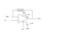
What's that resistor doing there?
Maby you had the intention of biasing the op-amp into class A, but that's not how it's done.
Does the other channel work?
Connected that way?
Maby you had the intention of biasing the op-amp into class A, but that's not how it's done.
Does the other channel work?
Connected that way?
emmmmmm maybe this is a good time to say this is my first project 🙂
I disconected the -In from GND but get the -In +In and Vout all between +6V and +12V (all identical). Is this a failure mode for an Opamp?
jnxw2
I disconected the -In from GND but get the -In +In and Vout all between +6V and +12V (all identical). Is this a failure mode for an Opamp?
jnxw2
It is a Current feedback Opamp and in the datasheet it says that to configure it for a Gain of +1 and a bandwith of 140MHz that you should use a 750Ohm resistor there. If you want more gain you need to chabge that value and connect the -In to GND via a resistor (Which is what led to the confusion in my head about connecting GND to the -In pin earlier)
Both seem to be acting in the same way, now im pretty sure they are wired up ok, Ive checked it hundreds of times, although I fear that at the beginning I might have connected the -Vs and +Vs wrongly 🙄
I just don't understand why there would be such an offset unless maybe they were fried...
jnxw2
PS If i connect a 1.5V DC source to the +Input the output drops to 3V then rises slowely to 14.2V!!

jnxw2 said:emmmmmm maybe this is a good time to say this is my first project 🙂
I disconected the -In from GND but get the -In +In and Vout all between +6V and +12V (all identical). Is this a failure mode for an Opamp?
jnxw2
We all started at our first project, sometime. No surprises there!
If you re-read my previous post, try to following the reasoning, you will understand that all inputs and the output necessarily are at the same potential (within reason, within the supply range). This is the way it is supposed to work.
Look at it this way: the opamp amplifies any difference between -in and +in, with a very high gain - a million or so!
So, if you put +1.5V at the +in, and the -in is still at zero, the output shoots up trying to reach a million times +in - -in which would be 1.5million volts. But it of course never gets there; when it gets to 1.5V, the -in also gets to 1.5V, the difference between +in and -in approaches zero and the output stays where it is, at 1.5V
Actually, there has to remain a small difference between -in and +in to maintain the output at 1.5V. That difference is (you guessed it) 1.5/a million.
Capisco?
So, this is how it should work. The drop to 3V and later rise to 14.2 indicates that there is something wrong with the connection of the supply and/or supply caps. Double check that again. Measure the voltages directly at the supply pins.
Jan Didden
Thanks for the explanation, i think i get it now. Your analysis was spot on, there was a problem with the power supply, the ahem fuses had blown due to some earlier "experimentation" 🙂 However armed with a new set of fuses and renewed hope I went about testing it again:
Channel 1
This one is easy, the +In is at +6V and the -In and Output are at 0V. When you connect the 1.5V DC source, the output does nothing, just stays at 0V. Now if I understand anything, that can only mean the IC has gone to where all good ICs eventually go...
Channel 2
At first it looked promising all inputs and outputs at 0V but then when you connect 1.5V to +In the output goes to -0.15V 😕
What would that tend to indicate?
jnxw2
jnxw2 said:Thanks for the explanation, i think i get it now. Your analysis was spot on, there was a problem with the power supply, the ahem fuses had blown due to some earlier "experimentation" 🙂 However armed with a new set of fuses and renewed hope I went about testing it again:
Channel 1
This one is easy, the +In is at +6V and the -In and Output are at 0V. When you connect the 1.5V DC source, the output does nothing, just stays at 0V. Now if I understand anything, that can only mean the IC has gone to where all good ICs eventually go...
Channel 2
At first it looked promising all inputs and outputs at 0V but then when you connect 1.5V to +In the output goes to -0.15V 😕
What would that tend to indicate?
jnxw2
Channel 1: agree with your analysis
Channel 2: don't know. If both channels were connected to the same faulty supply, both may have gone to the Great Electronic Manitou.
BTW, blowing fuses, frying opamps, starting over etc has a fancy name: most companies call it Research & Development. Hey, you're in R&D, what do you know!
Cheers,
Jan Didden
Well what do you know Ive made it! Im now a fully qualified electronics guru, fully versed in this black art, some people call a science.
Now on to designing that 150W class A amp I always wanted...
jnxw2
Now on to designing that 150W class A amp I always wanted...
jnxw2
Most R&D labs have a copy of Horowitz-Hill "The Art of Electronics", and a pile of dirt cheap TL071 opamps to play around with before actually smoking the AD811s.
Both warmly recommended.
http://www.amazon.co.uk/exec/obidos/ASIN/0521370957/ref=sr_aps_books_1_1/202-5325482-8443829
Both warmly recommended.
http://www.amazon.co.uk/exec/obidos/ASIN/0521370957/ref=sr_aps_books_1_1/202-5325482-8443829
- Status
- Not open for further replies.
- Home
- Amplifiers
- Solid State
- Opamp DC offset