A 24 bit 192kHz sound card will allow measurements up to half that frequency 88kHz), and the 24 bit resolution also means the noise floor of the system is well below -120dB, which is quieter than most electronics you will ever make.
We bought a used M-Audio card for 100 euro and Audio tester software for another 50 euros - works a treat!
Regards, Allen (vacuum State)
We bought a used M-Audio card for 100 euro and Audio tester software for another 50 euros - works a treat!
Regards, Allen (vacuum State)
> Where did you get those switches ?
Just stack multiple normal 3-stack ones to make them up, with some specially made mechanical parts to extend the shafts.
> And how did you implement the balanced part ? doesn't that add distortion ?
The output is just an inverting amp with an IC-buffer (HA5002) in the feedback loop. The input part is another opamp configured as differential amp. Using one of these LM4xxx opamps, there is hardly any additional distortion that you can measure.
Yes, I am sure there are many solutions for distortion measurement, not the least Audio Precision gear. But that is not the point of this thread.
Patrick
> Where did you get those switches ?
Just stack multiple normal 3-stack ones to make them up, with some specially made mechanical parts to extend the shafts.
> And how did you implement the balanced part ? doesn't that add distortion ?
The output is just an inverting amp with an IC-buffer (HA5002) in the feedback loop. The input part is another opamp configured as differential amp. Using one of these LM4xxx opamps, there is hardly any additional distortion that you can measure.
Yes, I am sure there are many solutions for distortion measurement, not the least Audio Precision gear. But that is not the point of this thread.
Patrick
The Harris IC's were in a Krohn-Hite analyzer I owned at one time -- it was single frequency, 1kHz.
Not to gild the lily too much, but the THAT Corp line drivers measure better than those from ADI.
Stupendous achievement Patrick, really well done!
Are a couple of months I'm thinking of building it.
I have already ordered the rotary switch, but are still undecided whether to use relays.
You had thought?
I realize the high number of relays necessary but this could, for example, allow a kind
of automatism in the tests. Of course, driving the relays with a digital logic.
Giuliano
I am posting this in the Solid State Forum as there used to be a couple of permanent threads for Bob Cordell. So I thought it is more appropriate here than elsewhere.
A couple of years ago I was attracted to Bob’s DIY distortion analyser by a htread at the Pass forum :
http://www.diyaudio.com/forums/pass-labs/91745-distortion-analyzer-recomendations-2.html#post1335073
Someone has actually made one :
http://www.diyaudio.com/forums/pass-labs/91745-distortion-analyzer-recomendations-4.html#post1356316
But that link no longer works. So I could perhaps post the photos here without getting into trouble.
Patrick
Nice job!! The photos you have supplied below are beautiful!
Believe me, I know how hard this project was! It was one of the most difficult tasks I have ever attempted. We sold over 200 sets of boards, but I don't know how many analyzers actually got built. We also had many requests for the state variable oscillator board. The oscillator design was inspired by an AES paper by Bruce Hofer, then of Tektronix, who later went on to become one of the founders of AP.
Gene Pitts, then Editor of Audio magazine, also deserves a lot of credit for encouraging me and letting me publish a 3-issue construction project.
Best regards,
Bob
This is probably a silly question but where can I find the schematics?
Hi Dave,
The schematics and the original construction article are published on my web site at Cordell Audio: Home Page.
Enterprising individuals can probably use most of the circuit design to do a better, easier job today. Better op amps, and alternatives to the big rotary switches come to mind.
I believe distortion on the state variable oscillator can be reduced by using a four-phase rectifier for the agc control circuit rather than the full-wave circuit that I used. The four-phase oscillator is made possible by the quadrature oscillator signals made available by the state variable nature of the oscillator.
One might consider analog multipliers in place of the control JFETs in the analyzer. One would certainly want to use an ADI true rms converter for the display rectifier.
Digital readouts for the input amplitude and distortion level also come to mind.
Cheers,
Bob
I appreciate fine analog circuitry and good dedicated function test equipment as much as anyone - but the lazy cheapskate in me can't ignore the possibilities of today's good&cheap digital hardware
the ESI Juli@ has up to 192K sample rate so it can make measurements comparable to the classic 80 KHz BW audio distortion analyzers
with a few active filter circuits to cut the fundamentals of the test signals and boost the error signal you can resolve with very good accuracy with better soundcards - spurious free dynamic range before the added filters can be ~100 dB, indirect measurement tricks with two channels generating IMD test tones and added gain/filtering can allow resolution of nonlinear test circuit behavior to exceed 160 dB
Free SciLab or other processing software can extract anything you can write the equations for from the .wav files
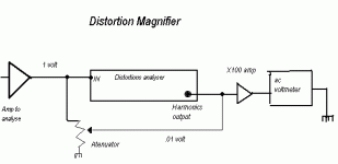
You're right; one can go a very long way these days with PC-enabled analysis. I have a Juli@ myself and it is very good. The Distortion Magnifier I built (described on my website) can increase the resolution of my analyzer, an analog spectrum analyzer, or a PC-based analyzer by 20 or 40 dB. This really enhances the ability of a sound card. It subtracts most of the source signal from a scaled version of the DUT output signal with precise amplitude and phase control. It is especially valuable for enhancing the 80 dB dynamic range of my HP3580A analog spectrum analyzer.
It is true, of course, that the 200 kHz controlled measurement bandwidth of my analog THD analyzer is valuable when measuring 20 kHz THD.
Cheers,
Bob
Dear Bob, is not that there are still PCBs to be purchased for this project, or you know someone has its ? I would be very interested!
Thanks and regards.
Giuliano
Unfortunately the boards are no longer available. They were laid out on my dining room table with Mylar and black layout tape. How things have changed!
BTW, they were single-sided.
Cheers,
Bob
The boards are easy. You just copy from the article to transparencies and expose on resist coated FR4s.
This was how I did mine.
One improvement I would definitely suggest is a distribution board to replace alll the wiring between the 3 PCBs and also place them somewhere easier for the switches. If I would ever do this again (never say never), I might also consider doing the whole thing with SMD, on one double layer board.
")
Patrick
PS Bob, I have many more photos. If you want any (e.g. for your website), just drop me a line.
This was how I did mine.
One improvement I would definitely suggest is a distribution board to replace alll the wiring between the 3 PCBs and also place them somewhere easier for the switches. If I would ever do this again (never say never), I might also consider doing the whole thing with SMD, on one double layer board.
Patrick
PS Bob, I have many more photos. If you want any (e.g. for your website), just drop me a line.
Last edited:
sadly there is not much description available...The Distortion Magnifier I built (described on my website) can increase the resolution of my analyzer, an analog spectrum analyzer, or a PC-based analyzer by 20 or 40 dB. This really enhances the ability of a sound card.
Regards
Attachments
sadly there is not much description available...
Regards
Hello
I think that Bob Cordell mean this description (untill the full description and schematics page will come);
Fom; Cordell Audio: Distortion & Distortion Measurement: Sensitive Distortion Measurement
----Consider a power amplifier that is producing 20 volts rms at its output with a THD of 0.001%. The distortion component will be on the order of 200 microvolts (100 dB down from the fundamental). The amplifier has a gain of 20, so the input is 1V rms. The output is scaled down by a factor of 20 to 1V rms, and the input is then subtracted from it. That leaves a distortion component of 10 microvolts. If a distortion magnification of ten is desired, an amount of the fundamental equal to 0.1V is then added to this signal, and the result is fed through a gain of ten. The result is a 1V rms fundamental and a 100 microvolt distortion signal to be fed to the THD analyzer. It can be seen that a 100 microvolt distortion signal on a 1-volt fundamental amounts to a signal with distortion down 80 dB, or 0.01 percent. The THD analyzer thus displays a THD value that is ten times the actual value. For a magnification of 100X, a 0.01V amount of fundamental would have been added back to the subtracted signal, and the result would have been multiplied by a 100X gain, resulting in a 1-Volt signal containing 0.1 percent THD.
Note that distortion and noise in the sinusoidal source are also reduced in the same relative proportion. As long as the DM is implemented with operational amplifiers with very low distortion, the distortion measurement floor of the resulting system is reduced by 20-40 dB.----
Bye
Gaetan
Last edited:
You're right; one can go a very long way these days with PC-enabled analysis. I have a Juli@ myself and it is very good. The Distortion Magnifier I built (described on my website) can increase the resolution of my analyzer, an analog spectrum analyzer, or a PC-based analyzer by 20 or 40 dB. This really enhances the ability of a sound card. It subtracts most of the source signal from a scaled version of the DUT output signal with precise amplitude and phase control. It is especially valuable for enhancing the 80 dB dynamic range of my HP3580A analog spectrum analyzer.
It is true, of course, that the 200 kHz controlled measurement bandwidth of my analog THD analyzer is valuable when measuring 20 kHz THD.
Cheers,
Bob
Hello
Your Distortion Magnifier would be very usefull for my old HP-333A distortions analyser.
Could you post a simplified working circuit of your Distortion Magnifier ?
I've made a drawing of my understanding of your ideas of this Distortion Magnifier, is my drawing are close to your ideas ?
Thank
Bye
Gaetan
Attachments
Last edited:
- Status
- This old topic is closed. If you want to reopen this topic, contact a moderator using the "Report Post" button.
- Home
- Amplifiers
- Solid State
- My implementation of the Cordell Distortion Analyser