Hi,
This is my first posting in here - so be not too strict with me")
I just found this schematics on the web.
Can anyone tell me, if it's worth a try?
I just want to build a really simple amplifier. It don´t have to be with shortening protection or anything like that or dc-protection for the speakers.
If you have any other good and simle circuit which runs on +/-45V let me know, please
This is my first posting in here - so be not too strict with me
I just found this schematics on the web.
Can anyone tell me, if it's worth a try?
I just want to build a really simple amplifier. It don´t have to be with shortening protection or anything like that or dc-protection for the speakers.
If you have any other good and simle circuit which runs on +/-45V let me know, please
Attachments
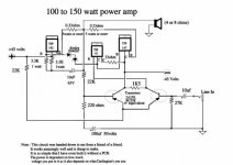
A couple of comments:
Sneak another 1N4007 in series with the other two so you end up with a string of three diodes.
Add a 100pF cap from B to C on the TIP41, that may be too big, but better safe than sorry.
Heatsink the outputs real well with either grease and mica washers, or rubber insulator pads.
The 27K on the input would be better if it was 22K, less chance for DC off-set.
Lower the 1K5 on the input transisors to 1K.
And very important: you must add a 0.1µF cap in series with 10 ohms and then put this combination directly across the speaker out terminals.
I expect this will do 75W at 8 ohms. I wouldn't run it at 4 ohms without reducing the supply voltages.
djk said:A couple of comments:
And very important: you must add a 0.1µF cap in series with 10 ohms and then put this combination directly across the speaker out terminals.
Just for me as a newbie, why is this so important?
What about using BD249/250 for the TIP142/147? Seems they can handle more current and are also Darlingtons...
technics said:If you have any other good and simle circuit which runs on +/-45V let me know, please
Did you look at this forum?
http://www.diyaudio.com/forums/forumdisplay.php?forumid=40
Example of very easy/simple circuit which you will find there, and can work from 45-0-45 (with LM3875 for example - which you can get as free sample
Attachments
Re: Re: simple Amplifier?
Thanks for this circuit - maybe I´ll give it a try. But occuring to the datasheet it will "just" have 56 Watts on 8 Ohm which isn´t very much on +/-45V...
I´d like minimum of about double this value (say 100Watts continous power on 8 Ohm), but capable of powering 4 Ohm with approx. 200Watts. So that bridging on 8 Ohm is possible.
I got here 4 power supplies with each delivers continous 350VA by trafo and enough caps to get stable power.
So I could build 4 identical amps and bridge each two of them to get 2 bridged channels.
Or I could bridge each two of the trafos and build 2 amps with each running at +/-90V...
JDeV said:
Example of very easy/simple circuit which you will find there, and can work from 45-0-45 (with LM3875 for example - which you can get as free sample
Thanks for this circuit - maybe I´ll give it a try. But occuring to the datasheet it will "just" have 56 Watts on 8 Ohm which isn´t very much on +/-45V...
I´d like minimum of about double this value (say 100Watts continous power on 8 Ohm), but capable of powering 4 Ohm with approx. 200Watts. So that bridging on 8 Ohm is possible.
I got here 4 power supplies with each delivers continous 350VA by trafo and enough caps to get stable power.
So I could build 4 identical amps and bridge each two of them to get 2 bridged channels.
Or I could bridge each two of the trafos and build 2 amps with each running at +/-90V...
I think a forward-biased LED would be better than a 12V zener, or you'll lose lot of drive in the positive direction, the output would probably clip at already 30V or something like that... the resistor values will have to be changed in that case too. I also think a LED is less noisy than a zener.
Re: Re: simple Amplifier?
lm3875 cannot run off of 45-0-45 ..
that's 90V, its max being 84V, that's a little too much
i wouldn't recommend more than 40-0-40 ..
just thought i'd clear that up
JDeV said:
Did you look at this forum?
http://www.diyaudio.com/forums/forumdisplay.php?forumid=40
Example of very easy/simple circuit which you will find there, and can work from 45-0-45 (with LM3875 for example - which you can get as free sample
lm3875 cannot run off of 45-0-45 ..
that's 90V, its max being 84V, that's a little too much
i wouldn't recommend more than 40-0-40 ..
just thought i'd clear that up
"Just for me as a newbie, why is this so important?(0.1µF+10R)"
If the amp doesn't 'see' a load at high frequency it can oscillate and blow up.
"What about using BD249/250 for the TIP142/147? Seems they can handle more current and are also Darlingtons..."
The TIP142/147 are plastic and rated at 125W at 25*C, in a real amplifier I wouldn't expect to see them run harder than 60W for the pair.
If you could find some 200W plastic darlingtons I wouldn't run the pair harder than 100W, and be sure and look at the secondary breakdown curves too. The TIPs start to fold back at 30V, even though they are a 100V rated part.
And when I say 60W or 100W I mean into the lowest impedance the amp will be expected to drive. If you make the voltage high enough to do 100W/8R you will not be able to drive 4R with only one pair of outputs. If you set it up to do 100W/4R, expect to see about 60W/8R
" but capable of powering 4 Ohm with approx. 200Watts. So that bridging on 8 Ohm is possible."
"Or I could bridge each two of the trafos and build 2 amps with each running at +/-90V..."
I would pick the ±90V option, less hassle than bridging. If you have a good heatsink and will only be diving 400W/8 you can get away with only three pair of MJ21193/21194 plus driver transistors. If you expect to drive 600W/4R off the same ±90V you will need five pair, 1000W/2R you will need eight pair.
If you want to use plastic, the MJL21193/21194 have the same die in a plastic case, but you will need to use TWICE as many to get the same reliability. Or you could do a tiered power supply with ±45V and ±90V rails and fewer outputs.
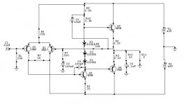
hugobross said:so this is what the amp looks like (after djk's suggestions):
best regards,
HB.
OK, I just built this circuit...
Testing it with +/-30V and 8 Ohm speaker by low power (approx. 1 Watt) sounded quite well. TIPs were going to be just lukewarm with no heatsinks mounted on them ;-)
So, when I have a little more time, I will plug the circuit to my +/-45V supply, test it with heatsinks and more power.
djk said:
If you want to use plastic, the MJL21193/21194 have the same die in a plastic case, but you will need to use TWICE as many to get the same reliability. Or you could do a tiered power supply with ±45V and ±90V rails and fewer outputs.
Hmmm, I have got plenty of 2n3055/MJ2955... do you have any circuit for them with power over 100W/8 Ohm?
They should work good for amps, I think...not as powerful as the mentioned above, but quite like the TIPs?
megajocke said:I think a forward-biased LED would be better than a 12V zener, or you'll lose lot of drive in the positive direction, the output would probably clip at already 30V or something like that... the resistor values will have to be changed in that case too. I also think a LED is less noisy than a zener.
good point! never thought about that!! with a LED instead of a zener R14 will be something like 68 ohm, and R9 something like 350 ohm. What's again the forward voltage of a LED, I think it was 1.4V right (for a red one)??
thanks again,
HB.
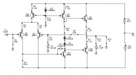
"Hmmm, I have got plenty of 2n3055/MJ2955... do you have any circuit for them with power over 100W/8 Ohm?
They should work good for amps, I think...not as powerful as the mentioned above, but quite like the TIPs?"
Motorola(ON Semiconductor)2N3055/MJ2955 can make a good amplifier.
Rail voltages should be limited to ±30V, they are only rated at 60V. If you bridge two amps built with one pair per channel it will put out 120W/8R~150W/8R depending on how 'stiff' the supply is. You will need two pair per channel(eight outputs total)to drive 200W/4R~250W/4R.
I would try and get the MJ21193/21194 parts instead. In the USA eight 2N3055/MJ2955 cost the same as four M21193/21194, and you only need four of the M21193/21194 to make a 150W/8R, 250W/4 amplifier running on ±60V. And no need to bridge either.
The other problem I see is with the 2N3055, how fast is it? Budget or no-name 2N3055s are usually slow, they're intended for power supply work so that's OK, but they won't work well for an audio amplifier.
If you need 100W or more, the M21193/21194 are hard to beat on a watt/$ basis.
Re: Re: Re: simple Amplifier?
Oops!!
Quit right. I don't want to sidetrack here, just a quick question. I don't quit understand all the specs on op-amps, but could you use this IC for a simple amp. running from 45-0-45 and what could max. output watts be?
elizard said:
lm3875 cannot run off of 45-0-45 ..
that's 90V, its max being 84V, that's a little too much
i wouldn't recommend more than 40-0-40 ..
just thought i'd clear that up
Oops!!
Quit right. I don't want to sidetrack here, just a quick question. I don't quit understand all the specs on op-amps, but could you use this IC for a simple amp. running from 45-0-45 and what could max. output watts be?
Attachments
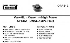
"DigiKey pn/OPA512BM-ND IC HIGH PWR/CURRENT OPAMP TO-3-8 Burr-Brown Corporation Division of Texas Instruments Bulk Power Single TO-3-8 High Power USD$ 84.51 qty 1"
This is one of those 'for that price ask me if I care' questions.
Real hard to heatsink an 8-pin TO-3 too.
You need a TIFF viewer for this:
Free TIFF viewer: http://www.alternatiff.com/
Transnova patent:
http://patimg2.uspto.gov/.DImg?Docid=US004467288&PageNum=1&IDKey=E9B6CEE066D8&ImgFormat=tif
This is one of those 'for that price ask me if I care' questions.
Real hard to heatsink an 8-pin TO-3 too.
You need a TIFF viewer for this:
Free TIFF viewer: http://www.alternatiff.com/
Transnova patent:
http://patimg2.uspto.gov/.DImg?Docid=US004467288&PageNum=1&IDKey=E9B6CEE066D8&ImgFormat=tif
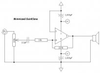
OK, how do we use the Transnova?
The easy way: Use a ±12V supply for the op-amp, use an LM1875(or the TDA equivalent)for the opamp, run a 10 ohm resistor to ground, hook up the bases of your output transistor pair straight to the output of the opamp. Use only Rb, Rd to set the gain, try 22K for Rb and 1K with 10µF in series for Rd, no Ra, Rc. Add a 22K resistor from the - input to ground. You may need a small cap in parallel with the 22K Rb, try 10pF~100pF as needed.
With eight pair of MJ21193/21194 and a ±90V main rail you will get 1KW out at 2R, no kidding!
Don't forget the 0.1µF + 10R across the speaker out. Use emitter resistors on the outputs, they all go to ground.
Is that simple enough?
A 1KW gainclone!
djk,
Numerous times you have pointed to the `Transnova' scheme or other simple ways of making ultra-high power amplifiers. Wish you could post a couple of schematics to make life simpler for lesser mortals. How about a rough hand drawn schematic that is scanned and posted as a picture or something else?
Thanks nonetheless!
djk said:
This link doesn´t seem to work...
But today I had some time to connect the "modded simple amp" to my +/-45V power supply - and it works!
It plays quite fine on 8Ohm speakers with low power. But I have a little problem concerning the volume-pots - which are in my case... If I use them (not at full volume), I always get a hum/noise. It isn´t a low hum/noise (no 50/60Hz) and has the shape of a saw-tooth (very clean!). When turning volume down hum/noise becomes bigger - when volume-pots are at max. position there is no hum/noise!
The Pots are 47KOhm and I used it for other amplifiers and had no problem with that!
Because the amp is connect to a mixer/preamp I actually don´t need them, but it would be nice
So where is the problem? Anyone has an idea?
On weekend - maybe sooner - I´ll try that amp on max. power output. Maybe I´ll also measure voltage and current.
"This link doesn´t seem to work... "
OK, let's try the front page instead. PN/4467288 if you still have problems. When you get there, click on 'images', you will need a TIFF viewer, and if you get an error message asking about 'active-X' you need to click 'yes'.
http://164.195.100.11/netacgi/nph-P...0&s1=4467288.WKU.&OS=PN/4467288&RS=PN/4467288
"But today I had some time to connect the "modded simple amp" to my +/-45V power supply - and it works! "
Great! Not bad for just a couple of $$.
"when volume-pots are at max. position there is no hum/noise!"
Not sure here, but try grounding the shaft of the pot. I've had problems with something like this before, hope you find it. Sounds ground related in any event.
- Status
- This old topic is closed. If you want to reopen this topic, contact a moderator using the "Report Post" button.
- Home
- Amplifiers
- Solid State
- simple Amplifier?