Wadaya think, are we the only people in here?
nope ;
I'm having (all the time ) real fun reading you wakoos .......
 but , unfortunately , I'm too occupied with other things , so I'm not able to participate with my peanut brain
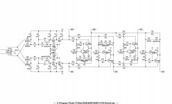
Completely dizzy: Muntzing round the SRPP totem...
I've never seen or drawn nothing like this before. Dunno how I come to it?
I think the tin foil helmet is becoming less and less effective over time...
Anyways, what exactly is this strange topology? And why does it seem
to be working? What more would it take to get this thing fireball worthy?
Needs a JFET up front, or something to provide the initial base current.
Its another unity gain wonder. Wonder how to get some voltage gain
out of it???
Attachments
Last edited:
Q1 never seems to shut completely off, but 100ohms across the
emitter of Q3 might draw a few extra milliamps just to be sure...
Its not in the drawing above, but probably should add it.
The sum of voltage across R1+R2, or maybe its the average...
Is held sorta constant by the series regulated thingie goin on
at the emitter of Q4 (does that makes it an SRPP?)
But then you got Q1 emitter down, Q4 emitter up, so sorta
halfways a diamond buffer too. Or one of them error correcting
something or others. I don't really know if thats how it works?
If the base currents required to drive Q3 and Q4 were equal
and opposite, the current in Q4 would be constant. But both
bases require a nonlinear swing of current, so Q4 is always
adjusting the sum of drive currents to keep the outputs in
proper balance.
Last edited:
Agh... Turns out its just another White Cathode Follower variant!
Only thing worse than a circuit that don't work, is one that DOES
but you can't explain why... Makin me even more nutz than usual.
Hopefully I got it figured now, we'll see what RBagger has to say?
Imagine the emitter of Q1 tied directly to the load, So's you can
see its actually behaving as a Sziklai Pair in conjuntion with Q3...
All of this sits atop an identical Sziklai Pair, Q2 Q4. Driven in
paraphase by the summation of errors detected.
For those reading, but not familiar: See Broskie's TubeCAD for
tech and background history on "White Cathode Follower".
The way I got it miswired, half Diamond Buffer style: Luckily
doesn't seem to ruin the WCF function. Q1 - Q4 does cancel
out an emitter voltage offset! I think the diamond buffer is
synergistic, but largely swamped out by the WCF effect.
Whatever... You got a new way to abuse four transistors.

Back soon.......................
Kirkwood your email bounces.
Last edited:
I cannot believe just discovering the writings of RoadBagger- wow. Someone else that actually knows something and even better can say it! It is really good to read someone else writing things I have said for years. Will be watching for more, YEA!
The part about load beta reflection of follower BJT is so true especially at RF designs and so many just do not understand. The reflection from a bad load is sent back into the amplifier to the last gain stage where phase margin collapses to minimum value and the amplifier breaks into oscillation. Most amps I have ever seen oscillate pretty easy because of this effect which results in a blown amp or at the least horrible sound. If phase margin can be maintained then different things happen. Load control can be one solution or amps with very low impedance final gain stages. The amps here when shorted simply blow the line fuse and no SOA protection is required. These amps will not oscillate under any condition that does not blow the line fuse immediately from severe overload condition as an example. When these other amps break into oscillation the bias and feedback both usually quit working and it is a very short path to smoke. Many amps tested here have operational points that are not to good and go into and out of variable gain or bias conditions (also mentioned by RoadBagger) and go into and out of oscillation during every cycle or more likely at a fast large transient of the signal under loudspeaker loads. Naim amp all do this as example and tick away in oscillation which become physiologically addictive to the point where only a Naim amp will do to Naim aficionados .
As RoadBagger indicates the probe at every location of the circuit should be the linear signal and never anything but. Unfortunately "but" is what I have found in almost every solid state amp ever tested. I used to run a repair shop so have seen a lot of commercial power amps and poked at them on the bench even more. If every point is not the linear signal, stop and fix it before moving on! Most will not do this. An amplifier is best thought of as "a filter with gain" and should behave as exactly that in every sense of the definition. Most amps do not.
Would really like to have talked long to the Dr. Slottow but living out here in the middle of dumbville (we do not even have evolution here) just does not lend itself to such activities and my asocial problems pushes me deep into the wilderness. All this fine tuning and great perspective from RoadBagger is wonderful- and what the internet if for. It is delightful to see such clear and concise writing and thank you for that. I hope to learn more and already have seen some very novel solutions to lowered distortion and faster circuits, hurray! With two different amps on the drawing board I am certainly not above learning and using great ideas unless someone says the idea is proprietary. Then of course not.
RoadBagger gets my "Most Fun" award! If more is better then most is best!
The part about load beta reflection of follower BJT is so true especially at RF designs and so many just do not understand. The reflection from a bad load is sent back into the amplifier to the last gain stage where phase margin collapses to minimum value and the amplifier breaks into oscillation. Most amps I have ever seen oscillate pretty easy because of this effect which results in a blown amp or at the least horrible sound. If phase margin can be maintained then different things happen. Load control can be one solution or amps with very low impedance final gain stages. The amps here when shorted simply blow the line fuse and no SOA protection is required. These amps will not oscillate under any condition that does not blow the line fuse immediately from severe overload condition as an example. When these other amps break into oscillation the bias and feedback both usually quit working and it is a very short path to smoke. Many amps tested here have operational points that are not to good and go into and out of variable gain or bias conditions (also mentioned by RoadBagger) and go into and out of oscillation during every cycle or more likely at a fast large transient of the signal under loudspeaker loads. Naim amp all do this as example and tick away in oscillation which become physiologically addictive to the point where only a Naim amp will do to Naim aficionados .
As RoadBagger indicates the probe at every location of the circuit should be the linear signal and never anything but. Unfortunately "but" is what I have found in almost every solid state amp ever tested. I used to run a repair shop so have seen a lot of commercial power amps and poked at them on the bench even more. If every point is not the linear signal, stop and fix it before moving on! Most will not do this. An amplifier is best thought of as "a filter with gain" and should behave as exactly that in every sense of the definition. Most amps do not.
Would really like to have talked long to the Dr. Slottow but living out here in the middle of dumbville (we do not even have evolution here) just does not lend itself to such activities and my asocial problems pushes me deep into the wilderness. All this fine tuning and great perspective from RoadBagger is wonderful- and what the internet if for. It is delightful to see such clear and concise writing and thank you for that. I hope to learn more and already have seen some very novel solutions to lowered distortion and faster circuits, hurray! With two different amps on the drawing board I am certainly not above learning and using great ideas unless someone says the idea is proprietary. Then of course not.
RoadBagger gets my "Most Fun" award!
If more is better then most is best!Where one sees linear voltage swings, you rarely see linear current swing.
Into a gate of a MOSFET one really prime example... And with linear current
swing into, oh say a loudspeaker, rarely you will see linear voltage. They just
do not work hand in hand together like that unless source and load impedance
is an absolute match. One factor has to hold the line, the other has to work
the load.
There is nothing invalid about voltage wildly all over the place and non-linear,
as long as current swing is holding true to the line, and vice-versa. I do not
think you can realistically hope to achieve sumaudio's linearity everywhere
paradigm without impossibly good impedance match everywhere.
And those who follow RF, know that lowest noise figure rarely coincides with
impedance match. I suspect a wild goose chase to achieve "the paradigm"
would only introduce other problems. But every reasonable thought outside
our too well traveled box brings the chance of advancing the art. Shouldn't
abandon the quest on my skepticism.
Never looked back....Never give up...Only learn
Whatever was written is a design philosophy. It is not a blind vision to all other thoughts and possibilities.
kenpeter has hit on a key point, impedance matching can solve many problems when it is available. Obviously impedance matching is not the goal for voltage source audio power amplification at the output as that is defined as a voltage source. No impedance match there. On the other hand, circuits inside the amplifier can be "defined" and topologies devised such that the voltage source output result appears as the filter with gain as mentioned within the current limits of the voltage source. Very few audio amplifiers have stable filter characteristics or transfer function. It is my belief there would be little difference in the performance and sound of various design and smoking an amplifier
  would not be so incredibly easy as it has proved many times over if this were not true. My amplifiers are all stable and blow the line fuse as protection. Stable filter characteristics and linear response at every stage was the key to that stability. No output load control, no output RC network, no hash choke, no Leech type (which is the proper single slope protection) current limiter, nothing but absolutely stable operation. This was not done with an extraordinary number of output devices either, 4 for the 120watt/8 ohm 350watt/2ohm and 16 for a 420watt/8ohm 1350/2ohm amps. All have this same feature, the line fuse is the short circuit and over current protection. Since learning how to make a stable amplifier I have never looked back.
You may wish to look at this as a chip example...
http://www.diyaudio.com/forums/chip-amps/163385-so-just-how-good-can-chip-amp-9.html
For low noise RF have been transformering up the 188 ohm balanced output Z of the receiving antenna to match into the about 800 ohms available with a low noise GAsFet. Is that what you mean? It is not important to answer that.
I am excited to say one of these days there will be a post here with my own watt sucking fireball amp. 300 watts in makes maybe 25 out...oh boy!
Whatever was written is a design philosophy. It is not a blind vision to all other thoughts and possibilities.
kenpeter has hit on a key point, impedance matching can solve many problems when it is available. Obviously impedance matching is not the goal for voltage source audio power amplification at the output as that is defined as a voltage source. No impedance match there.
On the other hand, circuits inside the amplifier can be "defined" and topologies devised such that the voltage source output result appears as the filter with gain as mentioned within the current limits of the voltage source. Very few audio amplifiers have stable filter characteristics or transfer function. It is my belief there would be little difference in the performance and sound of various design and smoking an amplifier would not be so incredibly easy as it has proved many times over if this were not true. My amplifiers are all stable and blow the line fuse as protection. Stable filter characteristics and linear response at every stage was the key to that stability. No output load control, no output RC network, no hash choke, no Leech type (which is the proper single slope protection) current limiter, nothing but absolutely stable operation. This was not done with an extraordinary number of output devices either, 4 for the 120watt/8 ohm 350watt/2ohm and 16 for a 420watt/8ohm 1350/2ohm amps. All have this same feature, the line fuse is the short circuit and over current protection. Since learning how to make a stable amplifier I have never looked back.You may wish to look at this as a chip example...
http://www.diyaudio.com/forums/chip-amps/163385-so-just-how-good-can-chip-amp-9.html
For low noise RF have been transformering up the 188 ohm balanced output Z of the receiving antenna to match into the about 800 ohms available with a low noise GAsFet. Is that what you mean? It is not important to answer that.
I am excited to say one of these days there will be a post here with my own watt sucking fireball amp. 300 watts in makes maybe 25 out...oh boy!
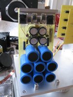
WattSuckingFireball#5
Finishing the construction and testing of the WattSuckingFireball#5. Were that all will go as theory and practice would incline, then P-Channel JFets and a new form of complimentary output stage will be in presentation this year. The hardest part of course being the stereo input step attenuator...........90 resistors.........It's Input stage features LSK389's LSK170's and LSJ74's this year
Finishing the construction and testing of the WattSuckingFireball#5. Were that all will go as theory and practice would incline, then P-Channel JFets and a new form of complimentary output stage will be in presentation this year. The hardest part of course being the stereo input step attenuator...........90 resistors.........It's Input stage features LSK389's LSK170's and LSJ74's this year
Burning Amp 2010 Limited Edition Tee Shirts
Linear Integrated Systems in conjuction with The Burning Amp Festival is offering pre sale of the new Limited Edition, Linear Systems 2010 Burning Amp Tee Shirts which feature "Watt Sucking FireBall #5"
The Tee Shirts are available in Black in sizes S, M, L, XL, XXL, for a price of $15.00. A good opportunity to guarantee you get the correct size and quantity you want now versus a more limited supply at the show. Your order can be placed thru the LIS website using a credit card. Please provide the size and number of shirts you want along with a phone number. LIS will contact you to confirm your order and recieve your credit card information (A/M, M/C, Visa) You pick up your shirts at the show. Non-show tee shirt sales will be conducted after the show based upon any remaining stock and sizes.
Tee Shirt Design: SlicART Sportswear
Tee Shirt Ordering: Linear Integrated Systems - Contact Us/Support
800-359-4023
Paul Norton
Linear Integrated Systems
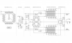
To run this Amp a fair amount of filter capacity is provided in its power supply producing little low frequency load distortion at high peaks. The power supply design is borrowed from last years amp but with additional stepped regulation for the preamp and front end drive. Liberal use of LS duals are in place strictly to minimize non-linearities in the audio current gain path. Though excessive, the TIM is much improved over a simpler Gm stage. Parts used in this Amplifier design are in current manufacture unlike some that were used in the 2009 WSF#4............As usual.................Kirkwood
Attachments
Last edited:
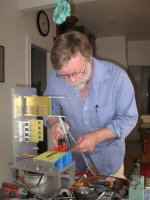
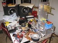
Why Kitchens Rule
The good part is that we've been married so long that this seems normal. DIY can potentially move into areas of concern, but where else does the creative process flourish, but where pie and coffee come from?
The good part is that we've been married so long that this seems normal. DIY can potentially move into areas of concern, but where else does the creative process flourish, but where pie and coffee come from?
Attachments
- Status
- This old topic is closed. If you want to reopen this topic, contact a moderator using the "Report Post" button.
- Home
- Amplifiers
- Solid State
- Watt Sucking Fireball Series