So...
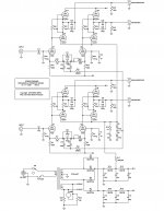
I was just having a chat with John Hall and he was commenting that the 1-1AMP circuit posted might not have enough voltage across the input fets to optimize noise and that the higher GM fet cascoded would consequently have a higher noise than the input fet placed in series with the same. YES. Noise increases with GM and the input FETs like any low noise FET will have a "sweet spot" when the right Vds is employed. This circuit illustration is for discussion purposes. The front-end is obviously a borrowed thing that I see frequently in a number of designs in various forms. Nothing original here, just a familiar place to start with other points to follow. That front end will be further assessed in time, but I suspect that somewhere in this sphere is a fairly thorough analysis of it. Illustrated first is the use of the matched transistor pair full Wilson mirrors, a habit of mine, current folding mania, then the output buffer. The advantage here is twofold. Normal NPN-PNP emitter follower buffers will, as I mentioned before, reflect the load impedance backward divided by the beta. The other phenom is an emitter follower's tendency to become unstable with capacitive loads due to input negative resistance C loading. The follower employed here is a variation of a circuit conceived by R. Fulks at General Radio. It's advantage is that here, a FET is used as the follower in a N-channel/PNP source/emitter output structure. The negative resistance loading effect is eliminated by the source follower, low noise impedance transform is provided by the FET and the FET source load is a low impedance emitter slaved to the source current demand by the upper PNP Iq sense feedback. The folded current summing node is now able to have it's highest gain potential being loaded by only a FET input capacitance and virtually no load resistance. Often a 20-50 pf cap is added to the current summing node to lower upper bandwidth and prevent oscillation. Slew rate is then dominated by I/C of the summing node. Not much different than the internals of an OP-AMP.
K-wood
PS: The Fulks buffer is also the basis for that cockamamie amplifier further back called the 2N4401-3, as an experiment in thinking I built it into a power amp with junk on the bench and modified it to have some gain.
Last edited:
Books
Ya know,
There are a number of books that I think are paramount to developing a focused perspective about audio reproduction. Many of these are available on the Web as downloads and some are just good to acquire as a shelf item to refer to. For those of you who have not stumbled onto this site, here is a large amount of time involvement you will find in conflict with the other things you know you should otherwise be doing. Technical books online
I think the Radiotron handbook 4th edition is also here but then, that’s one that I think needs a shelf. As well is the Audio Cyclopedia by Howard Tremaine copyright 1959 & 1969 and one that pops up from time to time, Amplifier Handbook by Richard F. Shea copyright 1966. Though the technology thoroughly illustrated here, is, as some feel, “Retro” the fundamental principles are basic physics and invariant with time. I can still hear the effect that the JBL Paragon system had on me driven at that time by a bias stabilized triode zero feedback amp way back. That effect of being there is always my goal and I think that linear transfer function is not as difficult a task as complex circuitry would otherwise represent. Though, it seems we usually get remarkably complex in order to arrive at the simplest solution. A speaker for instance, the magnetic path formed to push a field flux across a gap should be a highly permeable something and have a relatively constant cross-section so as to make the gap field uniform, past practice being steel. That situation only exists in practice with an electromagnetically generated field (EM). Permanent magnets (PM) all have permeabilities of unity even though when polarized they can have high B and H numbers. So the reaction of a voice coil to the EM gap flux is a tighter coupling than a PM speaker because it has no secondary field leakage gap made by the magnet. Though there are great advantages in using NdFeB magnets using a shorter gap across the magnet thickness to energize the VC gap and making a tighter coupling than thick Barium Ferrite ring plates, the coupling coefficient will not be as easily accomplished as that in a EM speaker field assembly. Though not immediately obvious, the EM structure for high clarity is simpler than a PM pole assembly to accomplish the same driver. Better coupling and damping in the “motor” action of a voice coil. So maybe it is “retro” but I like it, and I think there may be a lot of lost engineering that on second inspection might be an improvement toward the goal of ultimate fidelity………………….Massless Speakers.....BAF 2010
Prattling on…………………K-wood
Last edited:
Reply
nope !..............
does this mean investing in maglocks for future amt or linaeum experiment?
nope !..............
nope !..............
Field coil Maggie?
Huh? maybe you have that wrong John, isn't "Insultant" more the case here.........Tarring reality and feathering it with symbols,................... K-woodEveryone, I want to introduce you to K-wood Rough, one of the best engineering consultants in Silicon Valley. He can teach you, if you let him.

Last edited:
 , that Roadbagger deserve that .
Zenmod,
I've previously been on the phone with mr Bagger at his request, and was given
verbal permission and even encouragement to jack this thread. If thats what you
are suggesting I am carrying it too far??? I don't know references to JC or cam?
RB seemed to find my train of thought derailing in a positive way. Go figure...
So, I'm throwing him as many curveballs as possible. This tangent leads into
SRPP drive circuitry, and will shortly be revealed the relevance. Even though
deliberately revealing details slightly out of sequencer to make his head spin
new ideas (fill in the blanks) that might be even better...
If you want to split my tangent feedback off into a different (non-stickified)
thread, feel free to do so. But I am giving Roadbagger exactly the shakeup
he personally requested and finds useful. It was not done out of disrespect.
@kenpeter
naah ..... just disregard what I wrote .....
it was just my articulated fear that this jewel and nice flowing thread can mutate in something as BT thread...... parade of lost egos ;
take it as grumpy ZM's rambling .
it wasn't directed to you , in any case .
this time really Roger & over .
scusate from my side .
Ref: the venerable JC
Alright folks, put it all aside, the real reason for being here is to promote concepts that may or may not have merit, but at least have thought, sometimes of considerable mental bother to distractive conclusion. Though I may not subscribe to the train of thought that recommends prolific complimentary symmetric structures, I have used them liberally throughout many industrial circuit designs. Now that that phase of life is over, a return to the circuits of my origin often take a single polarity of voltage disregarding bias. The WSF is a derivative of the more palatable KRL/Peterson/Sinclair/Hall montage' and in part is represented here in its original form front end. Sorry about the vacuum thermionic parts but ya gotta start somewhere. For those who might dare to build it, I would be interested in your view of this theme. JC has been one of my mentors for some time, no capping here, OK? Other than communion with the venerable J.Curl I've mostly been talking to the mirror for this type of discussion and do appreciate real feedback.
As usual.....................K-wood
Attachments
Last edited:
And the other bad thought continues
Just trying to make a wierd thought ...........wierder
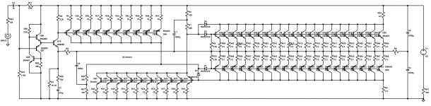
It just seems like a good idea to make a power amp out of $3.30 worth of transistors
"Tarring reality and feathering it with symbols" J. M. Ziman
K-wood
Just trying to make a wierd thought ...........wierder
It just seems like a good idea to make a power amp out of $3.30 worth of transistors
"Tarring reality and feathering it with symbols" J. M. Ziman
K-wood
Attachments
Last edited:
Although I have long ago downloaded my free copy of "The Radiotron designers handbook" I can't seem to find the other two books which Roadbagger mentions either on P.Milletts site or any where else on the internet for that matter.... which is a pity. I well remember making several visits to my local library to peruse "the audio cyclopedia" whilst still a teenager and would love to download a copy!
Although I have long ago downloaded my free copy of "The Radiotron designers handbook" I can't seem to find the other two books which Roadbagger mentions either on P.Milletts site or any where else on the internet for that matter.... which is a pity. I well remember making several visits to my local library to peruse "the audio cyclopedia" whilst still a teenager and would love to download a copy!
The Audio cyclopedia and Shea's amplifier handbook were mentioned only because of thier usefullness should they become available. If anyone knows how to turn one into a PDF without chopping up the book, I'd like to have my copies used for such a task.
K-wood
Vacuum Triodes are a great place to start upon the road to Solid State Triode Emulators.
And Anti-Triode Emulators... Such being merely the insultramentary anti-compliment of
of a single ended voltage amplifier (preferably one that behaves as a Triode.) Preserving
single endedness in push-pull, rather than complimenting it away...
For sake of ZenMod following along, Nelson's Aleph current source in 100% active helper
mode does EXACTLY the same thing. More on this later...
Now, you get some of this in SRPP totems. Tapping the plate end of the resistor we see
a single triode set the voltage, and the other (need not be a triode) maintain a constant
current into the plate. But this gives only the output (or drive) power of one SE Triode.
Or Tap the top end of the resistor, you get more power, and the low cathode resistance
into the circuit being driven. But as with all cathode followers, this is an asymetrically low
resistance, does not slew the same speed both ways... Try to drive too low impedance,
even before attenuation, you begin to see severe asymmetry.
I am advocating a node in the middle of the SRPP resistor as the ideal place to tap.
If voltage is held constant across this resistor by the upper device, then the sum of
voltage drops must add to this constant. What this means, is that currents into the
load are then forced equal and opposite (plus the quiescent). 2x power, but behaves
as-if 2x bottom device in parallel, rather than push pull. The top device need not be
a Triode, it can be any circuit that can hold said voltage drop across the resistor.
In fact, its a better match (for the real triode) if the top device isn't also a Triode.
the Cathode impedance of the top device becomes part of the resistor in the middle,
and pushes the center point of the balance toward the top end. Possibly so far up,
this virtual node might be inside the cathode resistance where we can't get at it...
And to justify the relevance, we see plenty of SRPP's drive stages in RB's designs.
And he has on more than one occasion stated a prefernece for differential push pull
circuits abusing devices that deliberately do not match. And thats exactly to where
this distraction is going...
Last edited:
- Status
- This old topic is closed. If you want to reopen this topic, contact a moderator using the "Report Post" button.
- Home
- Amplifiers
- Solid State
- Watt Sucking Fireball Series