Hmmmmmmm
I don't see anything wrong with copying, it's a good place to start while I work up a reasonable tutorial beyond broad generalities. Not sure how deep to go, it just takes some composition time.
K-wood
Can you teach me how to replicate that jfet front end? It doesn't seem right to just copy... I'm very impressed!
I don't see anything wrong with copying, it's a good place to start while I work up a reasonable tutorial beyond broad generalities. Not sure how deep to go, it just takes some composition time.
K-wood
I don't see anything wrong with copying, it's a good place to start while I work up a reasonable tutorial beyond broad generalities. Not sure how deep to go, it just takes some composition time.
K-wood
Whatever you decide to write, will be excellent. I'm a fan of choke loaded power differentials (my latest endeavor was at the BAF this year--the big fellow that took two people to lug to the listening table...
 ) and would enjoy learning more about employing the current/voltage controls you used in your design.
Thanks for what you've shared so far.
yes you're right ,,,maybe
Ok go for it, hobby businesses are at least fun.
Definitely fun, however, where it may be potentially true for the Audio business, though I have doubts about that as well, it definitely is not the case with industrial and scientific analog circuit design and implementation. The complex nature of an IC opamp and it's convolution of gains and nonlinearities over input to output drive and voltage swing can never be fully anticipated and straightened by a complex compensation. Most nodes of interest are not brought out on a pin, at least for me. Generally noted is the trend to need massive bandwidth with highly fed-back circuitry to maintain transient linearity while highly linear low loop gain parts require far less feedback and have measurably clean transient response with little or no compensation. Many times a hybrid of the two are used to utilize the DC acuity of the op amp and the linearity of a discrete. But in audio, DC acuity is a moot point, and since all of interest is AC, the loop gain argument tends to fall away in favor of a high linearity, low loop gain, to near zero feedback approach. When the discrete parts are both linear and wide bandwidth throughout, the phase distortion (group delay vs freq) is normally a non perceptible. This, being a primary influence in the transient IM, becomes evident in the air and image around a reproduction of properly recorded music and voice. ( that's my "hobby" voice talking) So, though having a long history of using op-amps and discretes for everything from particle beam metrology, to really clean Bass amps, I will probably prefer a highly linear low loop gain approach to SOUND.
K-wood
Last edited:
Hmmmm
Well, a few things would be the same and a few would need to change. The differences between the 2SK60 and the LU1014D are significant in a couple of ways. The input capacitance of the LU part is 10 times the input capacitance of the Sony part, so the driving impedance would need to be significantly lower in order to maintain reasonable slew rate for fidelity. The reverse transfer capacitance Crss is also rather enormous for the LU part and it would seem to necessitate output cascoding to reduce that miller effect on bandwidth and phase distortion. the LU type parts are very different than the vertical grid channel devices built in the 70's and in the effort that I was involved with in the 90's. So, they just need a bit more gate drive energy and circuit finess over frequency to be truly transparent. And you're right, it would be an interesting experiment. One other configuration that I've done in the past used Supertex depletion mosfets which are kinder to the designer with regard to the critical capacitances.
K-wood
Mr Rough,
do you mind telling what type of JFEts are used for the driver section ?
A version with LU1014D for the Sony power devices would be fun.
Well, a few things would be the same and a few would need to change. The differences between the 2SK60 and the LU1014D are significant in a couple of ways. The input capacitance of the LU part is 10 times the input capacitance of the Sony part, so the driving impedance would need to be significantly lower in order to maintain reasonable slew rate for fidelity. The reverse transfer capacitance Crss is also rather enormous for the LU part and it would seem to necessitate output cascoding to reduce that miller effect on bandwidth and phase distortion. the LU type parts are very different than the vertical grid channel devices built in the 70's and in the effort that I was involved with in the 90's. So, they just need a bit more gate drive energy and circuit finess over frequency to be truly transparent. And you're right, it would be an interesting experiment. One other configuration that I've done in the past used Supertex depletion mosfets which are kinder to the designer with regard to the critical capacitances.
K-wood
just for the sake of argument
Having a penchant for evolving tube circuits into silicon emulations of the same tends to make the signal path all majority carrier type devices,(N). So just to show that there is no prejudice here against minority carrier devices, (P), here is another watt sucking fireball amp made of 5 cent transistors and capable of >30watts. There is also the need to heatsink the face of every TO-92 to an aluminum plate which makes the mechanical layout interesting at best. The circuit is a self biased transistor array follower, modified to include gain by ratioing some negative feedback. Pretty clean and definitely cheap to build. The .01 caps are .01F or 10,000uF 35V each.
K-wood
Attachments
Last edited:
Yet another WSF or the Fun of it
This version of the WSF is the modern variation of the original design done 40 years ago in my parent's basement where a great deal of lernin' happened. This amp uses a MP5100 50 amp germanium transistor in series with a 4 ohm resistor as the collector load. 3.75 amps is the quiescent current for this output stage. The original had a finessed centering bias and a 5000uF coupling cap to the speaker, but still with the same results. I added the DC servo stuff on the later version because the feet just wont stay still. Though not terribly efficient, it has a remarkably clear response through the full spectrum. The drive is curiously booted to the output for bandwidth.
K-wood
Attachments
tube circuits into silicon emulations of the same tends to make the signal path all majority carrier type devices,(N). So just to show that there is no prejudice here against minority carrier devices, (P),
Majority and minority carriers can be either N or P. JFET's are always majority carrier devices be they N or P channel.
Semantics?
Not to be pedantic about it, that was a slight of hand comment for color but even the device designers will often call out in term, this: "A device in which the current is conducted by the charges dominant in the lattice is called a majority carrier device (e.g., electrons in n-type material, or holes in p-type material if the current is conducted by charges not dominant in the lattice, the resulting device is called a minority carrier device " (IRC) Though this is most often used in the description of channel devices like FET's, where current flow is conducted through a single type of semiconducting material and not passing through any junctions, the slight of hand was extending this to include "bipolar" junction devices for polarity sake. In the case of initial implied reference to WSF No.4, the entire signal path is N-channel devices and might be said, tongue in cheek, to be a majority carrier amplifier. Die sizes for "complimentary" devices are a good illustration of the difference. The P channel die compliment to it's N equivalent will be three times as large for the same doping regime to have "complimentary" characteristics. There will always be finessed parameters involving doping concentration and area to make the conductivity, capacitance and depletion efficiency match up, so areas can vary from 1.5 to 3 times in ratio when trade-offs are managed. Always will be the argument that there is no such thing as a truly complimentary device structure, and it's a good argument to engage when a Speyside single malt scotch is employed to refine the details therein, but a forum on this subject would turn into a full time job, and I have one of those. So thank you for the correction, I'll try to restrain my loose cannon for a more outrageous subject later.
K-wood
Majority and minority carriers can be either N or P. JFET's are always majority carrier devices be they N or P channel.
Not to be pedantic about it, that was a slight of hand comment for color but even the device designers will often call out in term, this: "A device in which the current is conducted by the charges dominant in the lattice is called a majority carrier device (e.g., electrons in n-type material, or holes in p-type material if the current is conducted by charges not dominant in the lattice, the resulting device is called a minority carrier device " (IRC) Though this is most often used in the description of channel devices like FET's, where current flow is conducted through a single type of semiconducting material and not passing through any junctions, the slight of hand was extending this to include "bipolar" junction devices for polarity sake. In the case of initial implied reference to WSF No.4, the entire signal path is N-channel devices and might be said, tongue in cheek, to be a majority carrier amplifier. Die sizes for "complimentary" devices are a good illustration of the difference. The P channel die compliment to it's N equivalent will be three times as large for the same doping regime to have "complimentary" characteristics. There will always be finessed parameters involving doping concentration and area to make the conductivity, capacitance and depletion efficiency match up, so areas can vary from 1.5 to 3 times in ratio when trade-offs are managed. Always will be the argument that there is no such thing as a truly complimentary device structure, and it's a good argument to engage when a Speyside single malt scotch is employed to refine the details therein, but a forum on this subject would turn into a full time job, and I have one of those. So thank you for the correction, I'll try to restrain my loose cannon for a more outrageous subject later.
K-wood
Scott, will you be at NAMM this year? Would like to meet up.
The chance is nil, but I do turn up in San Jose on occasion. I will send advanced notice next time.
As another funny coincidence, I live 2 blocks from the former Teledyne Crystalonics JFET fab on Sherman St.
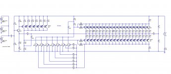
Not sure the purpose of your resistors in series with the
caps that bridge your split tail pairs in the 1st schematic?
I assume the intent was folding a cascode both ways to
make a theoretically perfect differential?
See you like the Wilson Mirror! Ever tried Blumlein's Garter
in that application? This was kinda my thought process how
to autobias a pair of tubes accurately enough for a toroid
OPT... I don't know how well it'd work under a JFET input
circuit like yours.
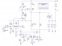
Drawing #1 is the pair of CCS shown in Drawing #2.
caps that bridge your split tail pairs in the 1st schematic?
I assume the intent was folding a cascode both ways to
make a theoretically perfect differential?
See you like the Wilson Mirror! Ever tried Blumlein's Garter
in that application? This was kinda my thought process how
to autobias a pair of tubes accurately enough for a toroid
OPT... I don't know how well it'd work under a JFET input
circuit like yours.
Drawing #1 is the pair of CCS shown in Drawing #2.
Attachments
Last edited:
Thoughts on differentials
Not sure the purpose of your resistors in series with the
caps that bridge your split tail pairs in the 1st schematic?
I assume the intent was folding a cascode both ways to
make a theoretically perfect differential?
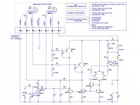
The story behind this design was pure inspired motivation. When someone suggested in late Sept. that I should look at this thing called a Burning Amp Festival, I decided to suggest building an amp, using all Linear Systems parts to demonstrate how good they sound in the linear gain chain of an ultra linear amp, to Paul Norton at Linear. So this amp became a reality from a clean piece of paper and a promise, to demo in 3 1/2 weeks. It started working at a demo level at 6AM of the show day. There were a number of choices that had to be made with no turning back because there was no time to make a change if something went wrong with some new idea. This design used a number of tried and true concepts from past designs, though never tried together. the input differential needed to have the lowest noise pair of current sources musterable. Matching of the LIS dual bipolars allows me to make the Wilson based dual source with fractional percent accuracy without thinking and with only 2 parts aside from the low noise current feeder made from a selected LSK170. Early in this series I said I didn't include any cross coupled anything like a Barrie Gilbert type preamp, (another long discussion) Because I wanted to keep the illustration of circuit concepts as simple as possible. The split resistor on the driver stage eliminates a resistive load imbalance that would come from the resistor biasing the source coupling caps. The 150 ohm total is there to be the degeneration/linearization of that stage, as all stages are controlled gain linear stages. The object in this design is to have the amp as linear as possible without feedback so the small amount of feedback employed will straighten but not interfere with transient IM performance. So, yes, theoretically perfect differential, but with the ability to independently steer the output bias condition without messing with the AC differential gain.
"See you like the Wilson Mirror! Ever tried Blumlein's Garter
in that application? This was kinda my thought process how
to autobias a pair of tubes accurately enough for a toroid
OPT... I don't know how well it'd work under a JFET input
circuit like yours."
Auto-biasing is an art that I developed in high school for putting Marshall Amp heads in line using a couple transistors in a differential balancing integrator for the grids. That way I could regulate the quiescent and use a mismatched Tungsol and a Sylvania, or whatever, without an imbalance in magnetizing current. That was how I financed an equipped basement amp shop in HS. I would do the same thing for a toroid output application, that is, to sense the cathode currents with as small a resistor pair as possible and use a differential integrator driving a pair of current sources to steer the grid bias into compliance. Most musicians in High School were as poor as church mice and getting matched tubes to achieve full output power from a Plexi-head was out of the question. Someday someone will find one of those old heads and wonder about that "hack" under the chassis. I have a PCB kit that I made for Guitar amp balancing that I used to sell. No more complicated than the one from 1969 but better.
K-wood
Drawing #1 is the pair of CCS shown in Drawing #2.
Last edited:
In the course of acoustic events
The Real Goal
In the grand scheme of things we strive to record and play back for all time to recall, a sound, like the smell of something that brings back a memory, reproduced the way we remember, the moment. There are certain phenomenon in audio reproduction that, when eyes are closed, will reveal that what is heard is real or reproduced. Much of that “false” image in reproduction is an intermodulation, fabricating non-original artifacts. What would be great is a holographic reproduction system. One that flawlessly reconstructs the entire field of acoustic influence from all angles, delays, environmentally influenced spectral convolutions, and most of all, true fidelity from copy to projection. Bringing this discussion out of the ethereal and making the bold assumption that a Louther, Manger, NHT, Magnaplane, Tanoy or the like will truly move air the way that it should be, an amplifier working in harmony with that load should be able to drive an electrical current with enough voltage compliance to satisfy uniform consumption of that energy but to do it without accelerating the load beyond it’s compliance limits. A perfect amplifier would have zero intermodulation distortion, constant output impedance, not zero or infinite, and if driven to a point of creating harmonic distortion, that it be compliant to the ear’s own asymmetric compliance limits and therefore acoustically invisible. A speaker system can be as guilty of hidden distortions as anything in the chain. Often unnoticed are non uniform speaker input impedances causing spectral notches in energy transfer through to the air. A speaker crossover should not only equalize the transfer function between radiating elements but also present a constant load to the amplifier allowing linear power transfer through its entire range. In radio frequency applications we call this broadband impedance matching, often not a trivial task. A filter will pass what it will and the remaining energy must go somewhere other than back down the throat of the amplifier. Though not efficient, adjacent filter dummy loads and attenuators are employed to feed off excess energy not transferred to the air and equalize the impedances throughout. When not, amplifiers having bipolar follower output stages will reflect an image of the load backward through beta demagnification to the base drive and so on, this is a loop gain shifter and it does have an effect. Reverse transfer capacitance, GM shifting drain to source V/I swings, Beta shift with collector current, Source and emitter resistance changes with current, all contribute to a series of complex interactive quantities that interfere with perfect linear transfer gain. As Time allows I’d like to illustrate some simple concepts toward that goal. An effort to keep this discussion on a conceptual basis first is to hold the “Concept” as primary, details of implementation may then have a stable framework for construction. Years ago at KRL’s Vudu Lab we observed subjectively that a perfectly clean audio source could be heard through a mix of other sources far better than the same source through a dirtier amp. When a clean source is heard, the perception is unmuddled by artifacts and can be said to have a high signal to noise ratio. The same source through a dirtier amp needs to be turned up in order to have the same perception of the source material being heard. In a constant noise field the clean source will be more easily perceived because all of its structure is a fixed power above the noise where the more distorted amp contributes noise to the listening field and must be turned up to compensate. I think this may explain why really distorted music is often played louder than should be humanly tolerated to say nothing about the attendant fatigue, and clean sources tend to be more comfortably level adjusted. So, the cleaner the source, the lower the volume and hearing damage. Not that I have an opinion, but it seems to me that poor tradeoffs have been made over time in favor of convenience and we may be loosing the perceptual ability to discern what is real and what is not. More later, after you cut this prattle to shreds…………………………
K-wood
Another thought
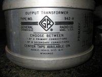
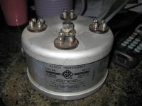
Transformer outputs are a wail of tradeoffs. If you want a Single ended drive the leakage reactance will be high so as to accommodate DC bias plus the differential swing about that point. In the P-P amp leakage reactance is managed depending on how much the tube quiescent current can be tolerated. Sloppier builds with more open window area in the core means the sloppier the tube balance can be. But little can be done with toroids accept balance, balance, balance. Low leakage, good coupling and high permeability tend to saturate toroid cores with little imbalance. It's a tight path to acoustic coupling efficiency as long as DC balances are corralled. There is a toroid tape winding technique available from Stangennes Industries in Palo Alto that spaces the permeable steel a bit with a dielectric coating. This provides some leakage in the core and makes a more forgiving toroid transformer. General Radio built a number of toroid transformers for audio, the 942-A comes to mind. it was used in the Gotham recording amplifiers some time back and driven with 811's I think. They used a winding technique called astatic winding which tended to reduce the imbalance issue by increasing some of the leakage and reducing distributed capacitance by this winding and isolated primaries. The isolated primaries were useful, allowing them to operate in parallel in a totem pole output stage developed by Donald Sinclair in 1952. This lowered the input impedance by 4 and effective distributed capacitance consequently upping the frequency range and uniformity of coupling coefficient to the speaker. The Sinclair P-P output stage is what I use almost exclusively in all the amps I do weather they are OTL or not. But then balance is always a good thing to do any way for other subtle influences in symmetry.
Prattling on....................K-wood
This was kinda my thought process how
to autobias a pair of tubes accurately enough for a toroid
OPT.....
Transformer outputs are a wail of tradeoffs. If you want a Single ended drive the leakage reactance will be high so as to accommodate DC bias plus the differential swing about that point. In the P-P amp leakage reactance is managed depending on how much the tube quiescent current can be tolerated. Sloppier builds with more open window area in the core means the sloppier the tube balance can be. But little can be done with toroids accept balance, balance, balance. Low leakage, good coupling and high permeability tend to saturate toroid cores with little imbalance. It's a tight path to acoustic coupling efficiency as long as DC balances are corralled. There is a toroid tape winding technique available from Stangennes Industries in Palo Alto that spaces the permeable steel a bit with a dielectric coating. This provides some leakage in the core and makes a more forgiving toroid transformer. General Radio built a number of toroid transformers for audio, the 942-A comes to mind. it was used in the Gotham recording amplifiers some time back and driven with 811's I think. They used a winding technique called astatic winding which tended to reduce the imbalance issue by increasing some of the leakage and reducing distributed capacitance by this winding and isolated primaries. The isolated primaries were useful, allowing them to operate in parallel in a totem pole output stage developed by Donald Sinclair in 1952. This lowered the input impedance by 4 and effective distributed capacitance consequently upping the frequency range and uniformity of coupling coefficient to the speaker. The Sinclair P-P output stage is what I use almost exclusively in all the amps I do weather they are OTL or not. But then balance is always a good thing to do any way for other subtle influences in symmetry.
Prattling on....................K-wood
Last edited:
Just a bit more
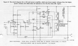
This is an example of a Sinclair-Peterson type push pull totem pole amplifier from the Oct. 1951 GR Experimenter publication. It puts both output tubes across the voltage rail to ground, cancels the magnetizing current as in a normal push pull and couples both primaries in parallel capacitively so the sending impedance is 1650 ohms instead of the usual 6600 ohm P-P. Of note is the fact that both output tubes are driven grid to cathode and the gain transfer function of both are identical as in the normal P-P configuration. Some stacked tube amps are driven so as to have the lower tube with transfer gain and the upper tube used as a unity gain follower with upper-lower drive correction through feedback. The Sinclair-Peterson architecture is a symetric drive impedance particularly when using triodes and requires little feedback.
This is an example of a Sinclair-Peterson type push pull totem pole amplifier from the Oct. 1951 GR Experimenter publication. It puts both output tubes across the voltage rail to ground, cancels the magnetizing current as in a normal push pull and couples both primaries in parallel capacitively so the sending impedance is 1650 ohms instead of the usual 6600 ohm P-P. Of note is the fact that both output tubes are driven grid to cathode and the gain transfer function of both are identical as in the normal P-P configuration. Some stacked tube amps are driven so as to have the lower tube with transfer gain and the upper tube used as a unity gain follower with upper-lower drive correction through feedback. The Sinclair-Peterson architecture is a symetric drive impedance particularly when using triodes and requires little feedback.
Attachments
Last edited:
- Status
- This old topic is closed. If you want to reopen this topic, contact a moderator using the "Report Post" button.
- Home
- Amplifiers
- Solid State
- Watt Sucking Fireball Series