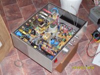
I'm trying to build a Class A power amp, but I'm facing some problem here, the MJE2955 is keep burning. When I switch it on, the speaker will come out loud humming sound. I have checked everything on the PCB ad the connection, but everything just seem fine and follow everything on the schematic diagram. Can any expert out there tell me what is going on here? Thank you.
Attachments
You probably need to show us some good pictures of your construction.
I took a quick look at the schematic and see no obvious problems. Rod Elliot doesn't publish things that are inherently dysfunctional, so it is likely that some aspect of your construction is problematic.
You are going to see pretty big amounts of power being dissipated in the output transistors, about 30w each, so big heatsinks are a necessity. Each (and probably every) output transistor will fry itself in under a second with no heatsink.
Stuart
FIRST rule.
Start up all new or modified projects with the mains light bulb tester inserted into the Live mains feed.
SECOND rule.
Do not connect any speaker until after you have proved to yourself that the amplifier is working properly.
Try changing the CCS 0r25 to 1r0 to get you started and able to measure some voltages.
Then we can try helping.
Last edited:
first step is to remove all MJ2955. Enhance the Ube resistor from 0R25 to 25R (25 ohms). Now you must have 26mA instead of 2,6A idle current (you have basicly now a preamplifier line stage).I'm trying to build a Class A power amp, but I'm facing some problem here, the MJE2955 is keep burning. When I switch it on, the speaker will come out loud humming sound. I have checked everything on the PCB ad the connection, but everything just seem fine and follow everything on the schematic diagram. Can any expert out there tell me what is going on here? Thank you.
In this mode you can make your troubleshooting (without risc of damage of your pnp power devices) until you have the right dc voltage values at all places. You cannot use as load resistance your hifi loudspeakers in this mode. Instead of this one use a load resistance of 1K. Check out with your scope, if there are unwanted oscillating effects. If it so, you must find the reason therefore in any case. Only about this way you can find out, if the reason for the damaged power devices comes from errors of your voltage driver.
Good luck
Last edited:
Make sure that your total supply isn't floating over 60V. Those transistors will permanently do funny things with only slightly more than that Vce.
If this is from Rod Eliott site - there should be a description of how to test all electrical parameters before connecting a speaker/source for listening test ?
kannan
If this is from Rod Eliott site - there should be a description of how to test all electrical parameters before connecting a speaker/source for listening test ?
kannan
you are right, here the regarded weblink:
20 Watt Class-A Amplifier
Hi there Matt'
I reckon you have probably sorted out that amp by now but I thought I would throw my 'two bob's worth'.
One discouraging thing that I have picked up on my latest amp is a connection between ground and my heatsink - despite using silicon rubber mounting washers on the TO-3P output devices and the other transistors that are mounted on the sink. If I measure the resistance from the sink to ground I can see that one way it is over 2k but when I reverse the leads on my multimeter I get about 30-to 40 Ohms, a quite significant amount of conductivity.
From this observation I get a mental image of output devices 'frying' like your pnp's did.
I know this has turned into another long story, but It may be worth looking at the conductivity of the heatsink itself, I know that some people skip the washers altogether and make a substantial gain in heat dissipation/transfer, but this would need to be factered into the design and construction from square one.
Getting back to my amp, - My thought is that the silicon washers have picked up some aluminium 'filings' from the drilling and tapping of holes inside the enclosure.
Have you/Did you sort that amp out? It looks very interesting an I have a picture of it on my hard drive. I would be keen to hear about it's performance and the power supply.
Cheers and good luck to you Matt.
20W amp
Hi there TJ,
I am hoping that we have just had a communication break down! You seem to have said...
"99% of the 2N3055/mj2955 transistor u brought from shop re factory reject"
Dear TJ, when you use the term 'u' or you it personalizes the topic. So,
If you have knowledge of counterfeit devices then you should share it with your mates; So what do you actually know about any 2N3055's or MJ2955's that are counterfeit or reject?
Do you work for RS in Malaysia?
By the way, the thread was not my own - I just dropped in to make a comment about some similar experiences. The devices Matt' used were MJE2955's in a TO-220 plastic package and are very unlikely to be counterfeit. You may be confusing them with the TO-3 Packaged MJ2955's and I personally don't think any respectable criminal would re-badge two of the cheapest components available to mankind.
Was this a 'typing mistake' or 'typo' or do you have some solid proof of this?
I want to be on record as saying that I have been very very happy with every order that has been supplied out of Thailand the Phillipines and China. Weather it be the back-yarders from eBay, or the Microchip company. The service over there is fantastic and the people are so helpful that I just want to buy more and more from them.
I am being sincere. Phil
Connundrum
Too right Andy. The funny thing is that each component checked out fine on the bench. The damn thing almost pumps the coil out of a 12 inch speaker i have jammed up under the table. It runs luke warm with Iq of 50mA per each of output devices or 40 - 50 degrees C at 100mA/transistor. It is so exciting to see that speaker moving for the first time!
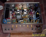
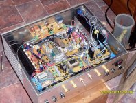
Wont be too hard to find the fault, and my first approach will be to peel the withered old second hand washers off the sink and replace them with newbies lightly coated in white grease. I think that some filings have fallen into that region and bridged the collectors to the sink. I will post a picture of my enclosure so you can all see my mistakes - #1 mistake is not using a single transformer with auxilliary windings for the preamp, DC protection, soft start and fans and so on etc etc But the box is done and I will soon have a result.
Measure resistance from output device collectors to heatsink. If there are shorts in there you must find and eliminate them.
Too right Andy. The funny thing is that each component checked out fine on the bench. The damn thing almost pumps the coil out of a 12 inch speaker i have jammed up under the table. It runs luke warm with Iq of 50mA per each of output devices or 40 - 50 degrees C at 100mA/transistor. It is so exciting to see that speaker moving for the first time!
Wont be too hard to find the fault, and my first approach will be to peel the withered old second hand washers off the sink and replace them with newbies lightly coated in white grease. I think that some filings have fallen into that region and bridged the collectors to the sink. I will post a picture of my enclosure so you can all see my mistakes - #1 mistake is not using a single transformer with auxilliary windings for the preamp, DC protection, soft start and fans and so on etc etc But the box is done and I will soon have a result.
Attachments
- Status
- This old topic is closed. If you want to reopen this topic, contact a moderator using the "Report Post" button.
- Home
- Amplifiers
- Solid State
- 20w Class A amplifier!