^I think your idea of a buffer inbetween the two would work well, but a triode would be simpler, right?
Simpler? I don't know. Were you planning to power the triode from your existing power supply?

se
Simpler? I don't know. Were you planning to power the triode from your existing power supply?
se
haha, thats true. but i'd end up using another supply for the buffer as well, most likely.
I actually still like the transformer idea, and still might apply it after some time with the triodes. That's the beauty of this design; the voltage and current stages are seperate
referring to post #34, the truth is, it was years ago and I don't remember what transformer I used and the rest of the circuit was sub-par anyway.
However, I have since discovered a better way, IM very HO. In a simplistic explanation, a phase splitting circuit can be made using a modified bridge topology with gate/base FB, phase lead compensation. You can use common mode feedback loops to bias the symmetrical bridge input stage wrt the common mode current of the VAS part; input a single end signal to the positive input and load both outputs with resistors. This will, no surprise, create both positive and negative phase outputs but the positive output voltage will be larger than the negative output because only one side of the bridge is driven. (The negative side is driven with the feedback from the positive side via a voltage divider.) But, if you load the positive output with a smaller resistor than the negative output, there will be a common mode error created wrt current flow in each side. The CMFB loops act as CM EC and correct for this ‘error’ by drawing the extra current needed to balance the bridge through the negative resistor load, increasing the magnitude of the negative output signal. With the proper resistor values the outputs can be made perfectly symmetrical, but it does in essence, shift the difference of output voltage to a difference of output impedance. In my circuit, the output phases remain perfectly symmetrical all the way up to 2.2MHz, which is as fast as my function generator will go.
The drawback is that the output Z can be affected by the loading of the next stage and therefore the next stage must have a relative high input Z so as not to have an effect on the CMEC. The whole circuit is intended to be a pre-amp anyway so it really isn’t a big deal. Also the circuit requires two DC servo circuits to control the common mode output. I posted this circuit quite a while ago but nobody seemed to have any interest so I just let it go. However, the proto-amp I built over 2 years ago that is based on this idea still works perfectly today.
The thread was something like ‘my bridge amp’ or ‘phase splitter’ or something like that, I don’t remember exactly.
I do agree that the transformer is MUCH simpler…..but better?
I'm not saying that a transformer as a phase splitter doen't work, or even an Op-amp phase splitter for that matter. It just depends on how much of a perfectionist you are.
Hi, i hope that the two following design can help here:
Doesn't help me.
I don't have Word.
se
CBS240,
---The thread was something like ‘my bridge amp’ or ‘phase splitter’ or something like that, I don’t remember exactly. ---
Maybe this one :
http://www.diyaudio.com/forums/soli...l-pseudo-differential-stages.html#post1214613
---The thread was something like ‘my bridge amp’ or ‘phase splitter’ or something like that, I don’t remember exactly. ---
Maybe this one :
http://www.diyaudio.com/forums/soli...l-pseudo-differential-stages.html#post1214613
Hi forr
The circuit in that thread is the first circuit that I discovered the idea of using CMFB to bias the VAS. But the latest circuit I am reffering too may not be on the forum, at least I can't find it. I am working long hours away from home right now, but I can sketch it out from memory, tomorrow. It's sleepy time now.
The circuit in that thread is the first circuit that I discovered the idea of using CMFB to bias the VAS. But the latest circuit I am reffering too may not be on the forum, at least I can't find it. I am working long hours away from home right now, but I can sketch it out from memory, tomorrow. It's sleepy time now.
Last edited:
Doesn't help me.
I don't have Word.
se
These designs was relative for construnction of an amp with only transformers as voltage gain element. (view thread "transformer as voltage gain element")
My simulation says that there is a good large bandwith for a gain up to 10 about. But putting in the second schematic an 1:1 transformer then it is good also as power stage for 2sk1530/2sj201 with the drivers. So if everyone put a simple S-E preamp gain stage to drive the transformer, then it's possible to realize a complete amplifier.
Francesco
Last edited:
Hi forr
You seem to be the only person here to have the slightest interest in using
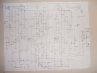
CMFB. I know it's a crude drawing and the extra info is relative, but it shows the basic idea. In the actual working circuit I built, the mosfets are J-fets that I hand matched. But I am curious how the matched mosfets, ALD1105, will sound used as the comp diff input stage. I'm fond of the idea of not having to match all those devices. I also plan to use ALD114804 depletion mosfets as the DC servo diffs. The BJT's labeled 1, 2, 3, and 4 is a THAT 340 matched array. All the BJT's labeled 1/2 or 2/2 is intended to be SOT-563 duel monolithic or maybe even SOT-963 if Pd allows it. I have hand soldered SOT-563 components and even SOT-923, but not SOT-963. Ultimately, the intent is to bake the SMD parts onto the PCB, but I haven't got that far yet. SOT-963 is awfully damn small. The jumper positions switch between single end or balanced input.
Perhaps one of these days, I will finish this project yet.
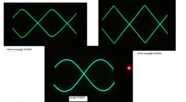
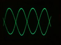
The sine wave shows both outputs of the entire amp at 1 MHz. (balanced VAS and output stages are not shown)
You seem to be the only person here to have the slightest interest in using
CMFB. I know it's a crude drawing and the extra info is relative, but it shows the basic idea. In the actual working circuit I built, the mosfets are J-fets that I hand matched. But I am curious how the matched mosfets, ALD1105, will sound used as the comp diff input stage. I'm fond of the idea of not having to match all those devices.
I also plan to use ALD114804 depletion mosfets as the DC servo diffs. The BJT's labeled 1, 2, 3, and 4 is a THAT 340 matched array. All the BJT's labeled 1/2 or 2/2 is intended to be SOT-563 duel monolithic or maybe even SOT-963 if Pd allows it. I have hand soldered SOT-563 components and even SOT-923, but not SOT-963. Ultimately, the intent is to bake the SMD parts onto the PCB, but I haven't got that far yet. SOT-963 is awfully damn small. The jumper positions switch between single end or balanced input. Perhaps one of these days, I will finish this project yet.
The sine wave shows both outputs of the entire amp at 1 MHz. (balanced VAS and output stages are not shown)
Attachments
- Status
- This old topic is closed. If you want to reopen this topic, contact a moderator using the "Report Post" button.
- Home
- Amplifiers
- Solid State
- Voltage gain stage for Non-NFB MOSFET current amp