No dear Bora...i have not...my new email adress is
dxpanzerfausten@yahoo.com.br
Maybe this is the reason i have not received....a pitty that... really, a pitty!
regards,
Carlos
........................................................................................................
Dx amplifiers dance too!
http://www.youtube.com/watch?v=o9KemZPUhbo&feature=rec-HM-fresh+div
I am sorry...the old adress, the panzertoo, was blocked because i forgot some
passwords...then they have blocked after some change of the password...the riminding phases i forgot, mine "best author"..when i have no best author, then i put something there and i do not remember that "something" i have entered.....so... i have lost that adress till the day i remember the best author i have written there.
ehehehehe.
regards,
Carlos
It's common practice for all manufacturers to use average SPL over the whole "ueasble" range for SPL 1M/1W. That includes the breakup peaks, which can be +10dB. Half-space reference sensitivity is easily calculated from T/S paramteters, and usually ends up some 3dB down from what's claimed based on average. It's probably about 94 dB, the same as similar drivers.
...
Good points wg_ski - thanks!
As for the Oversound specs, I suspect they are "overrated".
I would be surprised if the real sensitivity is over 90dB (1w/1m).
It would be a nice surprise though.

I would be surprised if the real sensitivity is over 90dB (1w/1m).
It would be a nice surprise though.
Surprise - if the published T/S are correct, it really is 96 dB. I ran the numbers in winisd. The catch is a 2mm x-max, which explains why the motor is strong enough to do this. Unfortunately, if Carlos unleashes his newest creation on them, they will likely be driven to distortion.
Strange thing... i have not dear Bora.... no email!
this email adress is new... i have no one blocked till now...no one into the block list, ignore list or spam list...all clean to everyone to enter...but i have not received your email till this moment!
Try the MSN adress: nanabrother@hotmail.com
The new email, the one i use, is :
dxpanzerfausten@yahoo.com.br
Atention!,,, exists something different into this new yahoo adress, it is from Brazilian Yahoo, because of that exists a BR into the end...means BRasil.
a pitty that... really a pity not to receive your email..... i am very frustrated because of that.
regards,
Carlos
I can't believe the advice being offered here.
One or two pairs of 1943/5200 cannot drive any 8ohm (to 435W) speaker reliably when powered by +-90Vdc supply rails.
Three pair of 1943/5200 can just drive an 8r0 resistor load as long as the output device case temperature is held below 45degC.
3pr cannot reliably drive a 16ohm speaker load to a 60degree phase angle.
reducing the voltage to +-84Vdc, 3pair @ Tc<=25degC and with a small transformer and low smoothing capacitance can just about drive a 16ohm speaker to 166W when phase angle <=45degrees.
1943/5200 are the wrong devices for use at high supply voltages.
Yes Andrew...all those things will be taken into account when produce the last, final
schematic..this is only my study...my experiences..nothing is ready..also my supply is not more 90 volts...now using 63 volts.
Also 90 volts supplies does not maintain voltage and usually drops.
Also the 63 volts supply does not maintain stable voltage under load... voltage usually drops.
thank you anyway.
regards,
Carlos
agreed, my model predicts what the DC rail voltage will fall to.Also 90 volts supplies does not maintain voltage and usually drops.
Then it looks at the effective Vce and Ic to calculate the transient SOAR plots.
The 1943/5200 hates high voltage supplies.
I will not use the 90 volts supply..not only the transformer is having big voltage
drop, but also i have no condensers to them.... 5000 uf each rail is not a good value, and this is all i have for a while (some will come at the end of this year).
Then i have decided to step down the voltage, another transformer and 62 volts... and this one will drop to 56 volts, more or less, with load... this way, three pairs will be enougth to 8 ohms load... and 4 pairs may hold 4 ohms... well... this gonna be tested here...do not worry, be happy!
I have several transistors... many pairs.... so i can put the amplifier to work full continuous power for hours long...if decision prove to be bad, we gonna see the transistors popping out.... real test will answer doubts... in such way the transistor itself will be the one will answer..if it survives, then decision was good...if not...decision was bad...simple that way.
Stone age method..alike the one used to test if girls were healthy thousand years ago...we have just to hit her with a bit piece of wood..direct into the head..if head cracks..then woman no good!
ahahahahah!
regards,
Carlos
Attachments

Last edited:
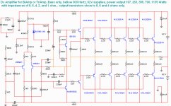
The 62 volts unit was tested and it is ready to go
Tomorrow i will show you the schematic....basically the Dx Amplifier, the Standard using 5 output pairs.
Power goes above 325 watts RMS into 4 ohms... a huge power.
Schematic is almost prepared (Dx Amplifier with some resistance values changed) and i will post it soon.
there's the input filter..it is for bass... distortion is very low...around 0.05% THD full power into 200 Hertz.... the input filter is external to the board.... and as the Dx Standard board was made to a single pair of output transistors, the others must be wired from the heatsink to the board..better to build a board with strips to base, coletor and emitter, also that can accept the emitter resistances.
I have tested using 3 output pairs..full power into 8 ohms..no problems.
regards,
Carlos
Here you have the schematic...tested into 4 ohms only
20 pairs may be needed to 1 ohms...but you gonna have more than a kilowatt of bass power, if your supply maintain 62 volts (Switching power supply) and provide you more than 15A each rail of current...hehehehe
5 pairs may be good to 8 ohms, 6 ohms and 4 ohms.... in the reality, to 8 ohms (200 watts RMS, continuous, undistorted, unclipped, 200 hertz, sinusoidal) you may use 3 pairs and will be safe...i have tested and 2 pairs have survived!
Text with details will be provided, off set adjustment, currents, voltages, bias adjustment, values, different parts you have compared to the Dx Standard and so on...you can use the same Dx Standard board available into Greg pages dedicated to the Dx Amplifiers... another extra board, to output power transistors may be needed and the power transistors into the board will need emitter resistances to be installed under (bellow) the main board.
Parts modified in value will be identified using colours.... parts that are not included into the pcboard layout provided at Greg home pages will be signed colour too.
Supply condensers, to each output impedance desired will be informed too as suggestion.
Soon i will be back...guaranteed!
This is for bass only..form 1 hertz to 200 cicles flat..and -3dB drop into 300 hertz... made for Dx BiAmp or Dx TriAmp systems... three power amplifiers to each channel, each one of them with their own volume control... all them using passive or active filter into the input...amplifiers tweaked (filtered) to the frequency selected.
Once again..this will keep you rid of room acoustics, speaker enclosure acoustics, home acoustics, your hearing agging problems (maybe), tastes and audio preferences...this way you gonna adjust without using passive crossover into the speakers...audio will go from the power amplifier directly to the speaker drivers.... a cable connection from speaker to power amplifiers having 6 wires into the cable... 2 wires to each one of the drivers used.
Maybe i gonna make a four amplifiers each channel..will see if needed.
All them with the super reliable Dx Amplifiers..the old bootstrapp delicious schematic used by several factories around the world.... guaranteed!
regards,
Carlos
Attachments
Hi Dx,
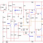
for a very high output current, I'd prefer to see a triple EF output stage rather than the two stage EF shown.
The two stage EF should work well with 8ohm speakers, for 4ohm I would recommend adding To126 pre-drivers.
I think the input and NFB capacitors could do with some adjusting.
The 100uF input, maybe 3u3F for 39k
and the 220uF NFB, maybe 330uF for 560r.
I do not like the To220 VAS device.
The lower driver is upside down.
The triple use to oscilate Andrew T...it is a hell problematic
about the to 220 you dislike into the VAS position..have a suggestion?
I am still listening..related capacitors, this may change a little...i am loving the way it is playing...but... we never know after some days listening and some more tweaks if we can or cannot make it better...it is always possible to improve...hard is to have the courage to stop...avoiding the "never ending" sittuation..that may be good for us, but bad to the ones wants to build..they do not like things that we go changing parts..you know...they cannot trust in something that tomorrow may be entirelly different and they will never know, because of that, if they gonna build the last revised schematic or not.... this driver people to be paralised, not to move.
So, i use to offer tested amplifier and do not tweak them anymore..to be something people can trust they have the last revised version.
regards,
Carlos
Last edited:
The VAS transistor is 2SC4793, and do not need to be low capacitance or high speed
has only to hold the peak to peak voltage..the amplifier is to operate into very low frequencies.
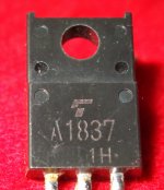
The drivers are 2SA1837 and 2SC4793, Aksa selected devices, black plastic case ones, that works great and holds high voltages.
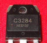
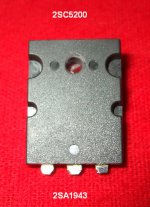
The output, my prefered ones are the big Sankens..the rectangular ones, alike 2SC2922 and complementary, also i love the 2SC5200 and 2SA1943..but there are several that can be used... power dissipation must be 150 watts or more, and current bigger than 10 amperes.... more than 200 volts maximum voltage from colector to emitter.... those are the most important things to worry about.
I am pointing MJE15031 device and complementary because they exist into my simulator..but they distort as a hell.... double the distortion compared to others alike BD139/140 (but this depends the voltage, as BD139/140 do not work into high voltages)...i do not like them..but they exist into the simulator and may work into the place shown into the schematic...reason why they are there.
Also i am pointing old fashion power transistors...because they exist into my simulator, and because they can work in that position...but....more modern ones will be a better idea.
Repeating..transistor is a transistor and it is no more than a transistors..all them have base, colector and emitter leads, some are black, others gray, others metalic...the shape may be different too..some a rounded, others eliptical, others square, others rectangular..well..different shapes and sizes..but they are transistors... they have maximum operational voltage, they have maximum current they can hold without melt..they offer you maximum dissipation (heat transference ratio) and gain....also they can work with very high frequencies (radio transmitters) or not..... but they are inter changeable, replaceable, having multiple possible substitutions....you know..use the ones you have that can hold 170 volts... To 220 to VAS and drivers and bigger folks to the output.
To the input use the ones you have that can work with 64 volts (our case)...even BC556 works fine there..not really needed to be the one pointed, despite the one pointed is very good...BC556 has inverted coletor to emitter when compared to the original Dx Standard differential transistors..have just to twist the one 180 degrees and solder it in place..just that!
There are preferences, fashion parts, easy to find parts, lower cost parts and higher cost parts..the ones you have at your shop, your town, your country, your internet parts provider and so on....do the best you can..engage your brain and take the decision you prefere.
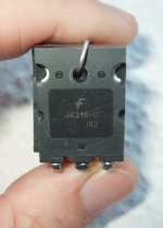
You have several suggestion watching schematics...there are several good transistors that often are used...i do use some Fairchild i have..some units Anonimous from our forum sent to me (thank you my dear)..they work fine too.
Transistors do not sounds... the just are resistance transfering devices...if you use the voltage they can withstand, they will be non linear as they are....and will work that way..the same as other replacement models... when you replace a transistor and found sounded better..was you brain that did that..self convincement, self persuation..you decided that..alike your wife..the most beautifull women in earth..really?.... well... i hope so.
regards,
Carlos
has only to hold the peak to peak voltage..the amplifier is to operate into very low frequencies.
The drivers are 2SA1837 and 2SC4793, Aksa selected devices, black plastic case ones, that works great and holds high voltages.
The output, my prefered ones are the big Sankens..the rectangular ones, alike 2SC2922 and complementary, also i love the 2SC5200 and 2SA1943..but there are several that can be used... power dissipation must be 150 watts or more, and current bigger than 10 amperes.... more than 200 volts maximum voltage from colector to emitter.... those are the most important things to worry about.
I am pointing MJE15031 device and complementary because they exist into my simulator..but they distort as a hell.... double the distortion compared to others alike BD139/140 (but this depends the voltage, as BD139/140 do not work into high voltages)...i do not like them..but they exist into the simulator and may work into the place shown into the schematic...reason why they are there.
Also i am pointing old fashion power transistors...because they exist into my simulator, and because they can work in that position...but....more modern ones will be a better idea.
Repeating..transistor is a transistor and it is no more than a transistors..all them have base, colector and emitter leads, some are black, others gray, others metalic...the shape may be different too..some a rounded, others eliptical, others square, others rectangular..well..different shapes and sizes..but they are transistors... they have maximum operational voltage, they have maximum current they can hold without melt..they offer you maximum dissipation (heat transference ratio) and gain....also they can work with very high frequencies (radio transmitters) or not..... but they are inter changeable, replaceable, having multiple possible substitutions....you know..use the ones you have that can hold 170 volts... To 220 to VAS and drivers and bigger folks to the output.
To the input use the ones you have that can work with 64 volts (our case)...even BC556 works fine there..not really needed to be the one pointed, despite the one pointed is very good...BC556 has inverted coletor to emitter when compared to the original Dx Standard differential transistors..have just to twist the one 180 degrees and solder it in place..just that!
There are preferences, fashion parts, easy to find parts, lower cost parts and higher cost parts..the ones you have at your shop, your town, your country, your internet parts provider and so on....do the best you can..engage your brain and take the decision you prefere.
You have several suggestion watching schematics...there are several good transistors that often are used...i do use some Fairchild i have..some units Anonimous from our forum sent to me (thank you my dear)..they work fine too.
Transistors do not sounds... the just are resistance transfering devices...if you use the voltage they can withstand, they will be non linear as they are....and will work that way..the same as other replacement models... when you replace a transistor and found sounded better..was you brain that did that..self convincement, self persuation..you decided that..alike your wife..the most beautifull women in earth..really?.... well... i hope so.
regards,
Carlos
Attachments
Last edited:
- Status
- This old topic is closed. If you want to reopen this topic, contact a moderator using the "Report Post" button.
- Home
- Amplifiers
- Solid State
- Dx TriAmp bass unit