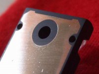
The back side, the transistor's back metal plate used not to be flat
this results the parts you see as copper colour are the parts are alike mountains and they would touch the heatsink..the lower parts, the valleys, the deep parts are the ones not touched by the waterproof, grain 500, sandpaper
The sandpaper was placed over a flat surface, a glass plate..and then i move the transistor to erode till turn it flat..you see material was removed into the parts you see copper...now it is flat.
If you do not do that, then the parts are higher, the projections, to the metal bubbles, the peaks, the hills, the mountains into the metal surface, will be the ones will touch the heatsink..this will reduce (a lot) the heat transference.
Check your transistors..you gonna be very surprised.
regards,
Carlos
Attachments
Now, some circuit details
Dx Amplifier – bass unit – to work with 62 plus and 62 volts minus
Was made (adjusted, tuned, tweaked) to work from 1 hertz to 300 hertz (-3dB)
Sensitivity – 1 volts rms to full rated unclipped output. (39.75 Volts rms)
Input impedance – 39K
Output impedance – 8, 6, 4, 2 and 1 ohm.. depending the quantity of power
transistors used into the output
Power amplifier details with sinusoidal input signal, and delivering 39.75 volts to
the load:
197 watts rms at 8 ohms, 200 Hz input with 1 volts rms of level, rail current
2.26A, and supply voltage at 62 volts to each one of the rails.
263 watts rms at 6 ohms, 200 Hz input with 1 volt rms of level, rail current
2.98A, and supply voltage at 62 volts to each one of the rails.
395 watts rms at 4 ohms, 200 Hz input with 1 volts rms of level, rail current
4.48A, and supply voltage at 62 volts to each one of the rails.
790 watts rms at 2 ohms, 200 Hz input with 1 volts rms of level, rail current
8.90A, and supply voltage at 62 volts to each one of the rails.
1135 watts rms, 1 ohm, 200 Hz input with 1 volts rms of level, rail current
14.9A, and supply voltage at 62 volts to each one of the rails.
regards,
Carlos
About fuses and electrolitic condensers to the supply
About rail fuses and supply fuses… do not use fast blow
Operating with 8 ohms speakers, then use 2.5A fuse to each rail
and 5 ampere fuse in series with the output (speaker)
Operating with 6 ohms speakers, then use 3.0A fuse to each rail
and 6 ampere fuse in series with the output (speaker)
Operating with 4 ohms speakers, then use 5.0A fuse to each rail
and 10 ampere fuse in series with the output (speaker)
Operating with 2 ohms speakers, then use 10 A fuse o each rail
and 20 ampere fuse in series with the output (speaker)
Operating with 1 ohm speaker, then use 15A fuse to each rail
and 30 ampere fuse in series with the output (speaker)
About filter electrolitic condensers to the power supply
Operating with 8 ohms speakers, then use 12.500uf each rail
Operating with 6 ohms speakers, then use 15.000uf each rail
Operating with 4 ohms speakers, then use 20.000uf each rail
Operating with 2 ohms speakers, then use 50.000uf each rail
Operating with 1 ohm speaker, then use 100.000uf each rail
regards,
Carlos
Continuing describing the power amplifier
Continuing with the specifications and details
The off set (Dc milivolts present into the output terminals due to
unmatching of transistor devices) is adjustable tweaking the 4k7
trimpot, pré adjusted to 3900 ohms (R23)..of set will be around
1.2 milivolts
Current crossing each power transistor is measured monitoring
voltage Dc, milivolts range, directly picking the voltage into the
emitter resistances extreme leads (0.33 ohm)… the voltage
to be measure may be 656 microvolts..and this results into 1.98
miliampere of current crossing each one of the power transistors
colector to emitter junction into stand by mode, with the input
shorted, so, no signal entering the amplifier circuit…. maximum
tollerable current to each transistor is 5 miliamperes each one.
Positive rail stand by current..having base shorted to ground, so,
no signal driving the amplifier…iddle mode, will be 37mA..and
this is measured using supply series protective resistance, that
resistance value is 10 ohms (10 watts minimum) and the voltage
measured directly into the extreme terminals will be 370 milivolts…
and this happens, only, when the power transistor emitter currents
are fine..or … measuring less than 2 miliampere to each power
transistors..and when they are 5 units…having more transistors, then
the current into stand by mode will increase depending the number of
transistors used.
Negative rail stand by current, having base shorted to ground, so, no
signal driving the amplifier… iddle mode, will be 29.4 mA…and this
must obbey all conditions written above….. this means 294 milivolts
measured over 10 ohms protective resistance.
regards,
Carlos
Some currents and more details
Long tail current is 1.42 mA, so, half of that to each transistor into the differential pair
Bootstrapp/VAS current is 9.68mA
Driver current is 4.86mA
External VBE multiplier has 1800 ohms resistance from base to colector and a series of resistances from base to emitter....the first resistance is a fixed resistance of 750 ohms (or other you choice) and the variable one (trimpot) is adjusted into 150 ohms (can be a 220 ohms trimpot)...so..total resistance from base to emitter is 900 ohms... set this way during start up.
regards,
Carlos
Post 44 had errors, reason why i am posting once again with corrections
Continuing with the specifications and details
The off set (Dc milivolts present into the output terminals due to
unmatching of transistor devices) is adjustable tweaking the 10k
trimpot, pré adjusted to 7200 ohms (R23)..of set will be around
1.0 milivolts
Current crossing each power transistor is measured monitoring
voltage Dc, milivolts range, directly picking the voltage into the
emitter resistances extreme leads (0.33 ohm)… the voltage
to be measure may be 750 microvolts..and this results into 2.2
miliampere of current crossing each one of the power transistors
colector to emitter junction into stand by mode, with the input
shorted, so, no signal entering the amplifier circuit…. maximum
tollerable current to each transistor is 5 miliamperes each one.
Positive rail stand by current..having base shorted to ground, so,
no signal driving the amplifier…iddle mode, will be 37mA..and
this is measured using supply series protective resistance, that
resistance value is 10 ohms (10 watts minimum) and the voltage
measured directly into the extreme terminals will be 370 milivolts…
and this happens, only, when the power transistor emitter currents
are fine..or … measuring less than 2 miliampere to each power
transistors..and when they are 5 units…having more transistors, then
the current into stand by mode will increase depending the number of
transistors used.
Negative rail stand by current, having base shorted to ground, so, no
signal driving the amplifier… iddle mode, will be 29.4 mA…and this
must obbey all conditions written above….. this means 294 milivolts
measured over 10 ohms protective resistance.
Differences in measurement around 20 percent plus and 20 percent
Minus are considered normal..do not worry with that.
Post 45 had errors too... reason why i am posting it once again with some different
numbers..sorry folks..my mistake.
Some currents and more details
________________________________________
Long tail current is 1.42 mA, so, half of that to each transistor into the differential pair
Bootstrapp/VAS current is 9.68mA
Driver current is 4.86mA
External VBE multiplier has 1800 ohms resistance from base to colector and a series of resistances from base to emitter....the first resistance is a fixed resistance of 1000 ohms (or other you choice) and the variable one (trimpot) is adjusted into 260 ohms (can be a 500 ohms trimpot)...so..total resistance from base to emitter is 1260 ohms... set this way during start up.
regards,
Carlos
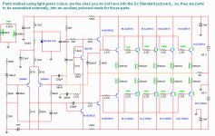
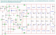
Parts that does not exist into the Dx Amplifier standard pcboard
The one you can find at Greg Erskine home pages:
http://users.tpg.com.au/users/gerskine/dxamp/
image attached.
regards,
Carlos
The one you can find at Greg Erskine home pages:
http://users.tpg.com.au/users/gerskine/dxamp/
image attached.
regards,
Carlos
Attachments
Adjustment steps... go and return procedure..the do it once again.
First install a 10 ohms resistance in series with the positive rail .. and them proceed doing the same with the negative line...you gonna measure DC volts or milivolts over this resistance..into the resistance extreme leads you should connect the voltimeter probe points... two voltimeters at same time if you have two units..not having, then do one each time...one measurement and then the next one.
Install a DC milivoltimeter into the output...positive probe point to the output line and negative probe point into the ground...this will monitor the off set.. this can be done simultaneously, having three multimeters, or do those things in sequence.
Short the input with a wire ... and do not forget to remove your short after finish your adjustment.
Switch the power on to the power amplifier.... some milivolts must appear into the protective resistances...and the bias trimpot must operate changing that value... if not..then you have mistakes into your construction..check the VBE multiplier and then the entire circuit for errors.
The off set voltimeter must show voltages smaller than 25 milivolts (maximum allowable by manufactures tradition..they say 25 is good)...the off set trimpot must operate changing the off set reading..if not!... then you have errors into your circuit construction...adjust to low reading..around 1 milivolt.
Then return to the bias and readjust it once again and check the off set another time too.... everything fine?... congratulations!
Open the short circuit you made into the input.... connect audio source and speaker and be happy.
Heatsinks size..... transistor heat.
Heatsink size will be good depending your output power.
To be simple and fast.... the 200 watts amplifier (8 ohms) will have 5 output pairs... so... you have 10 transistors.... if you install 10 aluminium blades, measuring 14 centimeters by 14 centimeters size (around 200 square centimeters exposed to the air to each one of the aluminium faces)..each one to one power transistor..then you will be able to work full power, unclipped sinusoidal continuous power, into a 30 degrees celsius environment, without troubles.
This same ammount of heatsink blades can hold twice this power..because music use to be average..so...maybe a 400 watts power amplifier will survive using those 10 blades, one blade to each power transistor, if the music has not continuous steady tones alike horns and such kind of compressed music.
These aluminium blades are 2 or 3 milimeters thick blades.... transistor mounted into the center and the aluminium fin (blade) into a vertical position...so...both sides (faces) will be sending hot air up.
This may give you an idea about.
regards,
Carlos
Last edited:
Transformer size... trafo power
Transformer power
The transformer must be a 44 plus 44 Vac transformer
To the 200 watts amplifier (8 ohms), the transformer power, to one single
channel of bass, will be 280 watts.
To the 260 watts amplifier (6 ohms), the transformer power, to one single
channel of bass, will be 370 watts
To the 390 watts amplifier (4 ohms), the transformer power, to one single
channel of bass, will be 550 watts.
To the 790 watts amplifier (2 ohms), the transformer power, to one single
channel of bass, will be 1100 watts.
To the 1135 watts amplifier (1 ohm), the transformer power, a single
channel of bass, will be 1850 watts.
regards,
Carlos
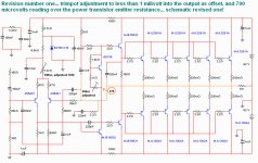
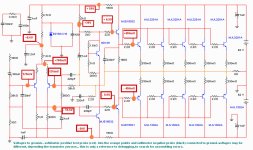
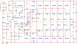
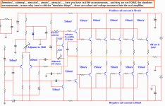
Revision made after a second check up into the real amplifier VBE voltages
Image one - a revosed(II) circuit for 62 volts supply
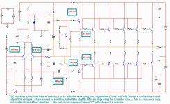
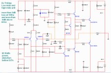
Image two - a 70 volt supply version asked by Orkut friend
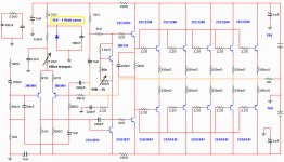
Image three - Real life measurements made... some VBEs, off set trimpot and bias trimpot settings
regards,
Carlos
Image one - a revosed(II) circuit for 62 volts supply
Image two - a 70 volt supply version asked by Orkut friend
Image three - Real life measurements made... some VBEs, off set trimpot and bias trimpot settings
regards,
Carlos
Attachments
Last edited:
You can use the amplifiers you have.
You can use any amplifier to drive TriAmp system
also to midrange and high frequencies (treble).
There’s no requirements to use the Dx amplifier.
I do use them because they are easiest available
to me…. You may have an advantage using the
Dx amplifier because the whole thing was adjusted
to this amplifier… as the input filter introduce losses
that must be compensated…also the follow up I use
to offer may be helpful…but..the truth of any facts is
that any amplifier will be good to this job… the main
philosophical idea is the passive filter and the tripple
amplification…what amplifier you gonna use is
secondary.
regards,
Carlos
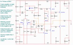
You may be asking yourself why those different supplies and output power?
The bass unit uses 62 volts and produces 200 watts into 8 ohms.
Bass is 60 percent of the total musical power... midrange is 30 percent and treble is 10 percent (normal balance of musical tones).
So, having 200 wiskies into the bass, i will need 60 to the mids and 20 to the treble.
So, my amplifier will have this same power output... or a little bit more into the treble (i am turning deaf because old)
Also because i will use three supplies, and i have, exaclty, those voltages at my home..i have all three transfomers.... i was lucky.
This idea (not mine..very old)...distorts less..you are sending less frequencies, less crowdy waveform to the power amplifier...you gonna have less frequencies to "beat" one each other... lower harmonic distortions will result.
Also..you do not need passive output filter..you can run wire direct to the driver.
Also you gonna be rid from issues related tune your speaker or to tune acoustically your home..having three controls each channel you will adjust to almost all acoustic environment.
Another advantage, separated supplies... 6 supplies will be assembled to a stereo..this will turn those amplifiers free from supply interactions.
The idea is great..the Dx BiAmp is working great and i am sure the TriAmp will be excelent too.
Of course, adjustments may be needed...will keep you informed..
380 clean undistorted, unclipped and continuous sinusoidal power will be sent to each channel speakers set... the amplifier will produce total of 760 watts rms... a very respectable power, if undistorted.
Be happy!
Carlos
Last edited:
- Status
- This old topic is closed. If you want to reopen this topic, contact a moderator using the "Report Post" button.
- Home
- Amplifiers
- Solid State
- Dx TriAmp bass unit