Thanks Joensd again...
The problem is just this.... I don't get that 1VDC on that problematic channel.
I have two diode bridges like in attachment.
On channel which work, I take that 35 VAC to protection circuit from other diode bridge and to other channel which not work, I take that AC from other diode bridge.

All wirings are OK.
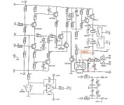
I have measured all resistors and diodes which are enclosed CNY17 optocoupler.
I have changed those CNY17 optocouplers from other channel to another.
Zero stage is OK too.

Now I feel that I'm electronic dumbass.")
The problem is just this.... I don't get that 1VDC on that problematic channel.
I have two diode bridges like in attachment.
On channel which work, I take that 35 VAC to protection circuit from other diode bridge and to other channel which not work, I take that AC from other diode bridge.
All wirings are OK.
I have measured all resistors and diodes which are enclosed CNY17 optocoupler.
I have changed those CNY17 optocouplers from other channel to another.
Zero stage is OK too.
Now I feel that I'm electronic dumbass.
Attachments
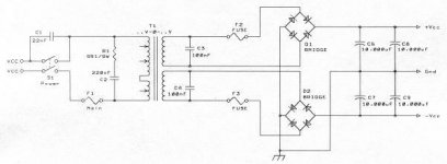
are both fase of the transformer connected like you need to if you would use 1 bridge, both fases at the diodes ( protectioncircuit thow ) should be 180° twisted.
There is now problem using 2 bridges but you should use same wiring as using 1.
If you dont want to change the wiring use a bigger elco for C9, but the shutdown will also be a little delayed witch is not so good after all.
Greetz Rudy
There is now problem using 2 bridges but you should use same wiring as using 1.
If you dont want to change the wiring use a bigger elco for C9, but the shutdown will also be a little delayed witch is not so good after all.
Greetz Rudy
Eccu, Rudy is right.are both fase of the transformer connected like you need to if you would use 1 bridge, both fases at the diodes ( protectioncircuit thow ) should be 180° twisted.
There is now problem using 2 bridges but you should use same wiring as using 1.
If you dont want to change the wiring use a bigger elco for C9, but the shutdown will also be a little delayed witch is not so good after all.
Greetz Rudy
With two bridges it´s tricky to connect it all up like Elektor intended to (using one bridge).
But as your first channel works it can´t all be that wrong.
How exactly did you wire the prot-PCB?
Wiring diagram would be handy.
Cheers
Jens - thinks Beavis is a dumbass
 I try that twisting tomorrow


No prob and gratulation!It's quite miracle that I get that other channel to work with first run
Very big thanks to both of you!
I hope that "twisting" helps
But.. where are the pics god damn it...

Cheers
Jens

Hello... I try (twist) swap those AC wires which goes to protection circuit, but it won't help nothing
But then I disconnect those AC wires from other diode bridge (which goes to good (working) protection circuit) and I connect those AC wires from bad (not working) protection circuit to that diode bridge and IT WORKS!
But I still not know why that won't work with that other diode bridge.
Both secondary windings are OK.
I measure both AC connections (from both diode bridges) to protection circuit and I get about 41VAC. Both works OK.
Do I miss something?
Is there any disadvantages if I connect both protection circuit to same diode bridge (same secondary winding)?
Will this effect somehow to other rail voltage because those AC wires are connected to diodes in protection circuit and other rail does not have this same kind connection?
But anyway.... now that fail reason clarified
Thanks to all on this thread!
You connected one secondary winding to the protection PCB?Is there any disadvantages if I connect both protection circuit to same diode bridge (same secondary winding)?
Sorry, I still can´t get your connections.
Where did you connect the two AC and the ground connectors from PCB according to the schematic above?
Cheers
Jens
... lets try this again, from the beginning
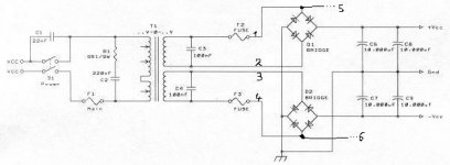
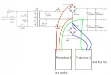
what we tried to explain is that you needed to switch wire 3-4 sow that after you switched them that you could wire 5 and 6 to the protection circuit. This makes no difference for the amp itself but for the protection it does.
i am not saying that you cant use the other bridge for the AC chenking off the protection, but isn't what we all want 2 totally seperated mono amps ...
i hope its little cleared out now
Attachments
Rudy said:... lets try this again, from the beginning
what we tried to explain is that you needed to switch wire 3-4 sow that after you switched them that you could wire 5 and 6 to the protection circuit. This makes no difference for the amp itself but for the protection it does.
i am not saying that you cant use the other bridge for the AC chenking off the protection, but isn't what we all want 2 totally seperated mono amps ...
i hope its little cleared out now
Yes I understand what you mean Rudy, but I only wonder why that both channel works when both are connected to same bridge and when both are connected to another bridge it wont work?

If you would connect the AC terminals only of the upper bridge to the protection PCB + ground you actually only check one of the rails which is not the intention. Voltage will be lower as well.If you connect the point marked '0' to your ground, then both the 25VAC (or is it 35?) points should be connected to the AC terminals of the upper bridge. All voltages at the lower bridge are always below zero, and the diodes on the protection circuit will never conduct.
I think Rudy´s explanation should make things clear.
Happy listening Esa!
Jens
- Status
- This old topic is closed. If you want to reopen this topic, contact a moderator using the "Report Post" button.
- Home
- Amplifiers
- Solid State
- Crescendo protection circuit?