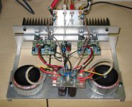
ultrachrome said:Finally found the time and patience to finish and debug. Had some problems terminating the primaries due to the varnished leads.
Sounds good so far. Still have some packaging issues to overcome.
I love the vestigial look. I really do need to find time to do mine up -- will be AKSA 25s thou.
dave
Thanks. I call it the cat killer. Luckily I have no pets or children. I need to come up with something different for the back plate that I mounted the heatsink on. But there's no reason why I can't enjoy it while I'm tweaking the chassis design.
It sounds really good so far. My first impression (after not listening to my stereo in about a week) was that the soundstage was quite a bit wider than my Adcom GFA-545II although placement of sounds is a bit more diffuse. The couple of CDs I've listened to (Beck, Pearl Jam, Sting) easily extended beyond the speakers. We'll see what happens over the next 10-20 hours.
It sounds really good so far. My first impression (after not listening to my stereo in about a week) was that the soundstage was quite a bit wider than my Adcom GFA-545II although placement of sounds is a bit more diffuse. The couple of CDs I've listened to (Beck, Pearl Jam, Sting) easily extended beyond the speakers. We'll see what happens over the next 10-20 hours.
Ultra,
The resolution and sound stage placement takes about 20 hours to mature. There will be some high end harshness, which will dissipate over this period. This is just a very low voltage cap bedding in, and you need to be patient.
My congratulations for a very tidy build. Something to be proud of!
Cheers,
Hugh
dual transformers
I always wonder how grounds of both channels, should be connected in amps with two transformers - in dual mono design. Aksa is one of the design where is one star ground (at psu board) where are coming all ground wires.
In most of cases I saw grounds run separately, like in mono block designs.
Is one of these solutions better?
I guess, in case with just one star ground, may be problem with ground loops.
Hi Jarek,
I believe you are right that separate star earths are a very good idea.
However, there are issues here. One, very obvious, is that most CD/DVD players, the signal source, use conjoined grounds for both outputs. But the other is more significant.
If we are to use two star earths, one for each channel, then the chassis cannot be connected to star earth and star earth must float. Then safety comes back to good quality transformers. In medical equipment this is normal policy, but often they also specify tighter insulation standards on the transformers.
Thanks for your input,
Cheers,
Hugh
ultrachrome:
VERY nice! Congratulations. and my sympathies to the cats.
Hey for you other AKSA builders and owners (and Hugh):
any of you ever dialed up the AKSA to low power (10-20 watt) Class A? (only after adding appropriate heat sinking and power supply enhancement, of course). If so, what did you think? I'm curious (again...)
mlloyd1
ultrachrome said:Finally found the time and patience to finish and debug...
Mlloyd1,
I have dialled up Class A on the AKSA during my R&D.
Up to 350mA of bias the bass control tightens, eventually ending up very powerful but dry. From about 125mA forward, the sound stage begins to close in, and some dynamics are lost.
I really do not recommend an AKSA in Class A. It was specifically designed for optimal Class AB, and functions best at these levels. To be honest, I've never heard a Class A with outstanding dynamics (even those of my own design! ) and really do prefer to stick with Class AB for its huge efficiency advantages as well.
Cheers,
Hugh
I have dialled up Class A on the AKSA during my R&D.
Up to 350mA of bias the bass control tightens, eventually ending up very powerful but dry. From about 125mA forward, the sound stage begins to close in, and some dynamics are lost.
I really do not recommend an AKSA in Class A. It was specifically designed for optimal Class AB, and functions best at these levels. To be honest, I've never heard a Class A with outstanding dynamics (even those of my own design!
) and really do prefer to stick with Class AB for its huge efficiency advantages as well.Cheers,
Hugh
AKSA said:
If we are to use two star earths, one for each channel, then the chassis cannot be connected to star earth and star earth must float. Then safety comes back to good quality transformers. In medical equipment this is normal policy, but often they also specify tighter insulation standards on the transformers.
I'm using two separate star earths in my GainClone amp (one for ea. channel). Initially I used one of the - speaker post in one of the channels to connect one of the star grounds to chassis (only one channel only). But in some setups, the was a noise generated in the other channel, which star ground was not connected to the chassis (for instance when somebody was close to the amp with a cordless phone). So I figured I had to connect both channels star grounds to chassiss and I did it with 2 pieces of wire from ea. star ground to a central point on the chassiss. The noise was gone and it works fine. Are we talking about same thing?
Peter,
You are lucky with that because your design is very compact (IMO). The influence of ground loop, which is formed by connecting signal grounds at two other points (at the source and the chassis star earth) is minimalised. When the construction is not such a compact we got a hum. The problem increasing when we join main safety ground to the chassis.
Always we agree to compromise... But which way is preferred from sonic view?
Discussed already on AC:
http://www.audiocircle.com/circles/viewtopic.php?t=2551&postdays=0&postorder=asc&start=0
In my opinion the AKSA sounds somewhat better with each channel floating.
Use Nelson Pass' thermistor method if you are concerned with safety, or a bridge rect + resistor for ground lift as per Rod Elliott.
Dave
Thanks Dave for the link.
My opinion on separating stars is like yours.
I have red you had tried to connect cold wire from the output to amp’s PCB. Don’t you think that wire from the center tap of transformer should be connected at the same point too? Otherwise we would have a big output current running with a small signal current together in one wire from PCB to the PSU.
Hi Jarek,
Dave and I have discussed this at length!
I agree with you.
My feeling is that signal return for the loudspeaker is actually from earth to the appropriate rail of the power supply. This means, naturally, that it should run through the filter caps. Consequently I would suggest running the star earth to the power supply pcb, albeit split right down the middle to keep left and right channels separate. This way there is no heavy power or speaker return current at the earth point on the pcb, and thus the delicate earth return to the star earth and tiny currents from the 100uF decouplers on each rail are not disturbed.
However, David's comments have been invaluable, and this is our only point of disagreement.
Cheers,
Hugh
- Status
- This old topic is closed. If you want to reopen this topic, contact a moderator using the "Report Post" button.
- Home
- Amplifiers
- Solid State
- New AKSA 55