Sure it can be maxed out to great performance... Just need to know the right handles...believe the key is in understanding of mirror impedances how to make something straight out of curved elements.
Anyway the main thing is to create a standalone OPS so you can make an amplifier where back EMF can't find its way back into the inputstage
Anyway the main thing is to create a standalone OPS so you can make an amplifier where back EMF can't find its way back into the inputstage
?
Hi!
please try to look at the harmonics descending up to 1MHz (switching hiss), is it higher for HCA than for AB buffer? during the simulation set the timestep 1n to get max accuracy of the results.
Have you tried to establish a similar comm?
I spent much time looking for ways to improve this HCA, but the only thing I found is that better be gone.
Hi!
please try to look at the harmonics descending up to 1MHz (switching hiss), is it higher for HCA than for AB buffer? during the simulation set the timestep 1n to get max accuracy of the results.
Sorry don't have the time at the moment....
Now the thing works on mirrors ...Have you tried to cascode them and maybe insert helper transistors also.. if the mirrors are not "perfect" errors are introduced. so by raising mirror impedance and making them more ideal the errors are reduced...this was the cryptic message in Joachims earlier post.
Now the thing works on mirrors ...Have you tried to cascode them and maybe insert helper transistors also.. if the mirrors are not "perfect" errors are introduced. so by raising mirror impedance and making them more ideal the errors are reduced...this was the cryptic message in Joachims earlier post.
Hi,
This is (in theory at least) a straightforward negative feedback system. Q305/307 basically have the output signal applied to the base's of a rush cascode pair and the input signal to the emitters. It is also send to an Emitter follower output stage.
If both signals are identical then the current through Q305/307 remains constant, so the whole biasing shebang also does not change.
If there is a difference between input signal and output signal the current theough the Q305/307 pair changes and changes the bias in order to correct for the difference.
Straightforward negative feedback. This circuit must be driven from a "Zero Impedance" Source (not absolute zero, but very low output impedance) to work correctly. Input impedance will be low (< 1KOhm) and non-linear (due to the jiggery pokery in the bias circuit).
I can see few if any advantages over the much simpler Haweksford Error Correction (which is basically the same thing) for the this circuit apparently designed to allow the marketing department more hyperbole (in case you wondered where the "hyperbolic conversion" comes from).
You can find a similar arrangement in the "Pax" Amplifier by Jan Didden, there he (ab)uses a current feedback Op-Amp with transconductance output to do the dirty work. Generally a quite elegant design, if you are going to scratchbuild something. I have also seen it done using generic Op-Amp in Technics (IIRC) amplifiers.
Ciao T
This is the HCA including component values...
Have not yet had the time to start simulation...
seem like it could be a good starting point for a power-buffer for a non global feedback amplifier-circuit
This is (in theory at least) a straightforward negative feedback system. Q305/307 basically have the output signal applied to the base's of a rush cascode pair and the input signal to the emitters. It is also send to an Emitter follower output stage.
If both signals are identical then the current through Q305/307 remains constant, so the whole biasing shebang also does not change.
If there is a difference between input signal and output signal the current theough the Q305/307 pair changes and changes the bias in order to correct for the difference.
Straightforward negative feedback. This circuit must be driven from a "Zero Impedance" Source (not absolute zero, but very low output impedance) to work correctly. Input impedance will be low (< 1KOhm) and non-linear (due to the jiggery pokery in the bias circuit).
I can see few if any advantages over the much simpler Haweksford Error Correction (which is basically the same thing) for the this circuit apparently designed to allow the marketing department more hyperbole (in case you wondered where the "hyperbolic conversion" comes from).
You can find a similar arrangement in the "Pax" Amplifier by Jan Didden, there he (ab)uses a current feedback Op-Amp with transconductance output to do the dirty work. Generally a quite elegant design, if you are going to scratchbuild something. I have also seen it done using generic Op-Amp in Technics (IIRC) amplifiers.
Ciao T
Here is a supplier:I need a HCA circuit IC BA3122N Cant seem to find one anywhere. My Yamaha MX-1 has one dead channel until I can find one. Anyone have a parts unit?
http://www.chsinteractive.co.uk/electrical-components/misc/ax930-ba3122n-i-c-yamaha.htm
ask also there:
http://www.elw-elektronik.com/
check additional about this number: XG609A00
about the same topic there is a second thread:
http://www.diyaudio.com/forums/solid-state/142233-yamaha-hca-circuit.html
Last edited:
BT told me he was keeping his place up in the hills around here because he thought he would return. Never did. Still down there where there was more interesting work possibilities. BTW - I did same bias circuit but on input stage of a line amp I published way back in TAA.Last time I talked to him he was an electronics rep down in
Arizona or New Mexico.
For those, who are wondering, why this and that doesn't simulate well:
As with any good feed forward approach, the performance of the whole thing is much better than the performance of the two canceling parts.
The AB stage is only made to provide raw power at moderate distortion level, while the Class A (HCA) stage is only to cancel the distortion of the other stage (a few mV to a volt or so) plus the phase shift of the output inductor of the AB-Stage (!!!) and otherwise behave like a very low impedance (virtual ground) node, which provides minimum current induced distortions.
A well made FF-Setup of this type is able to cancel any kind of distortion of the main amp by at least 40dB. The big trick is only to not add new distortion to the total signal and that's where the HCA complication comes in. So for those who are on the minimalist side: This is not for you.
In order not to repeat myself:
The MX-10000 amplifier is probably the lowest distortion amplifier being built between 1987 and 1998 (when Halcro came on the market). There are a few of the same vintage which come close on paper (Technics SE-A100, 5000 and 7000), but none integrates so well into a given setup like the MX (ultra faithful and transparent reproduction combined with raw power).
It is really a joke that all the Krells, Burmesters, Pass Labs, Levinsons etc. with all their pimped-up 60ies circuitry have such a huge reputation, while there is one amp out there, which is a few decades more advanced (technically and sound wise) and still is not recognised at all as a major achievement.
Yamaha should do itself a favour and build the MX again (together with a really good pre amp indeed and some NSX-100000 speakers...).
For those, who are wondering, why this and that doesn't simulate well:
As with any good feed forward approach, the performance of the whole thing is much better than the performance of the two canceling parts.
The AB stage is only made to provide raw power at moderate distortion level, while the Class A (HCA) stage is only to cancel the distortion of the other stage (a few mV to a volt or so) plus the phase shift of the output inductor of the AB-Stage (!!!) and otherwise behave like a very low impedance (virtual ground) node, which provides minimum current induced distortions.
A well made FF-Setup of this type is able to cancel any kind of distortion of the main amp by at least 40dB. The big trick is only to not add new distortion to the total signal and that's where the HCA complication comes in. So for those who are on the minimalist side: This is not for you.
In order not to repeat myself:
The MX-10000 amplifier is probably the lowest distortion amplifier being built between 1987 and 1998 (when Halcro came on the market). There are a few of the same vintage which come close on paper (Technics SE-A100, 5000 and 7000), but none integrates so well into a given setup like the MX (ultra faithful and transparent reproduction combined with raw power).
It is really a joke that all the Krells, Burmesters, Pass Labs, Levinsons etc. with all their pimped-up 60ies circuitry have such a huge reputation, while there is one amp out there, which is a few decades more advanced (technically and sound wise) and still is not recognised at all as a major achievement.
Yamaha should do itself a favour and build the MX again (together with a really good pre amp indeed and some NSX-100000 speakers...).
The main reason therefore is that in Europe and USA / CDN is not much replicated from the Far East, as the reverse is the case.
No one expected from Yamaha, that such an innovative topology is in use in their power amp model.
Nobody has investigated therefore Yamahas HCA topology, although the circuit was not confidential and therefore it was inside of the associated service manual (some developers believe - as indeed we know - to have eaten the wisdom with spoons). Otherwise, this HCA topology would be more often in use for audio, so I think.
The topology isn't very complicated (go to the PDF attachment from post #40). But the exact adjustment for min. distortion would be difficult.
Last edited:
On the latest "transistor gijutsu(トランジスタ技術)" , a japanese electronics magazine,
an article of HCA circuit written by inventor of it , Masao Noro.
http://toragi.cqpub.co.jp/tabid/587/Default.aspx
related articles
http://toragi.cqpub.co.jp/Portals/0/download/2012/lv1/circuit/HP.pdf
http://toragi.cqpub.co.jp/tabid/541/Default.aspx
I scanned and summarized it for this forum.
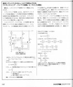
(attached img003)
On 図G(illust. G) obviously Iin = IC1 + IC2
Next , from fundamental characteristics of transistor,
VBE1-VBE3 = Kln(IC1/ID1)
VBE2-VBE4 = Kln(IC2/ID4)
circuitly,
VBE1-VBE3 = -(VBE2-VBE4)
then
Kln(IC1/ID1)+Kln(IC2/ID2) = Kln(IC1・IC2/ID1・ID2) = 0
therefore
IC1・IC2 = ID1・ID2 (fixed)
we can obtain linear Iout with amplifying IC1 and IC2 with power current mirror.
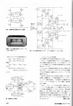
図H is a current type HCA circuit,the output stage of MX-10000 .
But general power amp's output stage is voltage buffer,
so voltage type HCA circuit is invented .
図I is voltage type HCA circuit of AX-2000 MX-2000 AX-2000a.
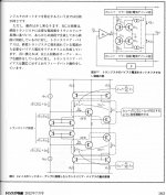
img005 and img006 explains another non-cutoff circuit : translinear bias circuit.
translinear bias circuit feedbacks output current while HCA is open loop like working.
an article of HCA circuit written by inventor of it , Masao Noro.
http://toragi.cqpub.co.jp/tabid/587/Default.aspx
related articles
http://toragi.cqpub.co.jp/Portals/0/download/2012/lv1/circuit/HP.pdf
http://toragi.cqpub.co.jp/tabid/541/Default.aspx
I scanned and summarized it for this forum
.(attached img003)
On 図G(illust. G) obviously Iin = IC1 + IC2
Next , from fundamental characteristics of transistor,
VBE1-VBE3 = Kln(IC1/ID1)
VBE2-VBE4 = Kln(IC2/ID4)
circuitly,
VBE1-VBE3 = -(VBE2-VBE4)
then
Kln(IC1/ID1)+Kln(IC2/ID2) = Kln(IC1・IC2/ID1・ID2) = 0
therefore
IC1・IC2 = ID1・ID2 (fixed)
we can obtain linear Iout with amplifying IC1 and IC2 with power current mirror.
図H is a current type HCA circuit,the output stage of MX-10000 .
But general power amp's output stage is voltage buffer,
so voltage type HCA circuit is invented .
図I is voltage type HCA circuit of AX-2000 MX-2000 AX-2000a.
img005 and img006 explains another non-cutoff circuit : translinear bias circuit.
translinear bias circuit feedbacks output current while HCA is open loop like working.
Attachments
Last edited:
That's very cool information !!
Regarding who is inventor and to put it into the correct historical context:
The HCA version with feedback to the emitter resistors (as used in the MX-10000) was basically invented by Blomley and further studied and published in L'Audiophile (France) by Jean Hiraga and Gerard Perrot (aka Hephaistos of Lavardin) in early 1980ies.
I think the MX-10000 HCA design is based on these studies. The ties of Jean Hiraga to the Japanese Audio scene was pretty tight at these days, but finally it is not clear in which direction the information was flowing, but ulimately Blomley was the initiator.
Regarding the "voltage version", a very similar approach (with a little HEC in it) was earlier invented and patented by Manfred Schwarz (of Wega Germany, developing for Sony ESPRIT division in the late 70ies). This circuit was commercialized by Sony in their ESPRIT amplifiers TA-N900, N901 and N902.
Basically one can say, that most likely the honor of the invention of "HCA" goes to UK, France and Germany, but the honor to transfer it into a series product goes definitely to Japan.
A very similar thing happened with Technics Class AA (aka VC-4), which is inspired by Class S (By Sandman) and Current Dumping (by Walker), but realized in a way that it actually does, what Walker only claimed ...
The Masao Noro-Patent for HCA can be found here:
Patent US4404528 - Output amplifier - Google Patents
This was filed after the L'Audiophile articles, so they never got Patent protection outside JP and US.
Masao Noro has a huge amount of Patents on his name. I would not expect that he invented all that (In case this is the case he must be a "workaholic" kind of a super genius).
Anyhow, it is very common to big Japanese Corporations, that they have only one or a few official inventors (Very often the Engineering Director or the like), so sometimes a person, who is higher in hierarchy gets the honor of being the inventor. So there is a big chance, that another Yamaha employee or a conglomerate of several engineers ist the real "inventor". So the understanding of the term "inventor" is pretty different in Japan ...
Japanese members please correct me, if I'm wrong !
On the latest "transistor gijutsu(トランジスタ技術)" , a japanese electronics magazine,
an article of HCA circuit written by inventor of it , Masao Noro.
2012?7?????????????????????
related articles
http://toragi.cqpub.co.jp/Portals/0/download/2012/lv1/circuit/HP.pdf
???????USB????????????
I scanned and summarized it for this forum
(attached img003)
On 図G(illust. G) obviously Iin = IC1 + IC2
Next , from fundamental characteristics of transistor,
VBE1-VBE3 = Kln(IC1/ID1)
VBE2-VBE4 = Kln(IC2/ID4)
circuitly,
VBE1-VBE3 = -(VBE2-VBE4)
then
Kln(IC1/ID1)+Kln(IC2/ID2) = Kln(IC1・IC2/ID1・ID2) = 0
therefore
IC1・IC2 = ID1・ID2 (fixed)
we can obtain linear Iout with amplifying IC1 and IC2 with power current mirror.
図H is a current type HCA circuit,the output stage of MX-10000 .
But general power amp's output stage is voltage buffer,
so voltage type HCA circuit is invented .
図I is voltage type HCA circuit of AX-2000 MX-2000 AX-2000a.
img005 and img006 explains another non-cutoff circuit : translinear bias circuit.
translinear bias circuit feedbacks output current while HCA is open loop like working.
Very interesting report. How difficult it would be a translation from the Japanese language in English or another European language with help by the tools from follow URL?
ICR and OCR technologies intergration - solutions for developers from ABBYY
BTW - for "Class-S" check out this thread/article:
http://www.diyaudio.com/forums/solid-state/122655-class-s-amplification.html
"Sandman, A. 'Class-S: A novel approach to amplifier distortion', Wireless World, September 1982, pg. 38" (not online available)
and this terms for google: FFEC (Feed Forward Error Correction)
P.S. At first look the topology of the output stage from the PDF
http://toragi.cqpub.co.jp/Portals/0/download/2012/lv1/circuit/HP.pdf
looks similar to that one from Linn's power amp model "Klout" - go to the attachment
Attachments
Last edited:
thanks.
I didn't know such the studies outside of japan.
I have heard the name Jean Hiraga at japanese audio scene,
but I thought he is mere a man of trading company.
I had read a article of Technics's classAA on japanese audio magazine.
According to it, technics's engineer explained classAA is based on current dumping and stasis circuit.
I have never heard class S by sandman .
Last edited:
I made a mistake:
The HCA-Patent from Masao Noro is the following one:
Patent US4803441 - Amplifying circuit - Google Patents
It describes everything in English language ...
The other Patent I quoted earlier is referenced by the Noro application (copy and paste error).
The HCA-Patent from Masao Noro is the following one:
Patent US4803441 - Amplifying circuit - Google Patents
It describes everything in English language ...
The other Patent I quoted earlier is referenced by the Noro application (copy and paste error).
P.S. At first look the topology of the output stage from the PDF
http://toragi.cqpub.co.jp/Portals/0/download/2012/lv1/circuit/HP.pdf
looks similar to that one from Linn's power amp model "Klout" - go to the attachment
Andreas,
the Linn only has fixed current sources in the bases of the CFP output transistors (instead of resistors).
This helps stabilizing the bias currents and improves linearity. If these current sources were driven by the input of the power stage (by feed forward), then you would have something similar to the "voltage HCA" or Manfred Schwarz' error correction scheme.
The Schwarz circuit doesn't have a name anywhere so far so I would define it here as Schwarz Error Correction (SEC).
One of the Schwarz Patents can be found here:
Patent US4439743 - Biasing circuit for power amplifier - Google Patents
That this circuit works very well can be seen on the Sony TA-N902, where the output stage gives 0.005% distortion (at 20kHz, half power) without any global feedback.
Just another question: I once saw the L'Audiophile articles in your literature collection. Are you able to find them again and say us if my comments (based on memory) are correct. (Hiraga, Hephaisthos, early 80ies) ???
Just another question: I once saw the L'Audiophile articles in your literature collection. Are you able to find them again and say us if my comments (based on memory) are correct. (Hiraga, Hephaisthos, early 80ies) ???
L'AUDIOPHILE - French TOC-overview 1977-1988 - found by
Audio bricolos (death in the meantime):
CD1: Première série : 43 numéros, de 1977 à 1988:
ELECTRONIQUE, théorie, recherche
Alimentations
Influence des circuits d'alimentation -1- le cas du préampli Kanéda. (G.Marec)
L'influence des circuits d'alimentation -2- Amélioration d'une alimentation non régulée
L'influence des circuits d'alimentation -3- Amélioration d'une alimentation non régulée
L'influence des circuits d'alimentation -4- Préampli Kanéda: le contrôle de l'extrème grave (G.Marec)
Vieilles recettes ou nouvelle cuisine pour nos alimentations (Héphaïtos)
Vieilles recettes ou nouvelle cuisine pour nos alim -2- expérimentation objective (Héphaïtos)
Vieilles recettes ou nouvelle cuisinne pour nos alimentations -3- Analyse subjective (Héphaïstos)
Vieilles recettes ou nouvelle cuisinne pour nos alimentations -4- réalisations (Héphaïtos)
Amplification
Analyse d'un schéma pas comme les autres : le Quad 405
Aspects de l'électronique (Y.Neveu)
Mesure de la distorsion par intermodulation dynamique (1) (M.Otala)
Analyse comparative des méthodes de mesure de distorsion (2) (M.Otala)
La distorsion dans les amplificateurs (3)
Un avis sur la perfection électronique
L'IIM ou distorsion dans l'interface ampli/enceinte
Réflexions sur la réalisation et l'emploie des égaliseurs graphiques
Le comportement des amplificateurs en régime musical
L'analyse tridimentionnelle et les amplificateurs chez Technics
Evolution des circuits amplificateurs (J.Hiraga)
Performances en bruit d'un préampli associé à une cellule (P.Faugeras)
Les amplis Kanéda classe A, 15W, 30W, 40W, 50W et70W (J.Hiraga)
Distorsion par transitoire -1- définition et origines (P.Faugeras)
Distorsion par transitoire -2- Les solutions (P.Faugeras)
La distorsion dans l'amplificateur de puissance (Héphaïstos)
La distorsion thermique (Héphaïtos)
La distorsion thermique - tube contre transistor (Héphaïtos)
L'étage de sortie de l'ampli -1- réflexions théoriques (Héphaïtos)
L'étage de sortie de l'amplificateur -2- (Héphaïtos)
L'étage de sortie de l'amplificateur -3- (Héphaïtos)
L'étage de sortie de l'ampli -4- solutions moins classiques (Héphaïtos)
L'étage de sortie de l'ampli -5- la classe A quadratique (Héphaïstos)
L'étage d'entrée de l'amplificateur -1- : étude théorique (Héphaïtos)
L'étage d'entrée de l'ampli -2- le différentiel classique (Héphaïstos)
L'étage d'entrée de l'ampli -3- différentiels insolites (Héphaïstos)
L'étage d'entrée de l'ampli -4- expérimentations complémentaires (Héphaïstos)
ebay offers of this magazine:
eBay | Revue L'audiophile Collection
partly online available
L'tage d'entre de l'ampli : -2- le diffrentiel classique (Hphastos)
L'tage de sortie de l'ampli -1- rflexions thoriques (Hphatos)
L'tage de sortie de l'ampli -4- solutions moins classiques (Hphatos)
L'tage de sortie de l'ampli, 5me partie, la classe A quadratique (Hphastos)
http://www.pure-hifi.info/pdf/Le ma...4- solutions moins classiques (Héphaïtos).pdf
Perhaps French members can translate.
Last edited:
a certain similarity you will find by this topology:The Schwarz circuit doesn't have a name anywhere so far so I would define it here as Schwarz Error Correction (SEC).
One of the Schwarz Patents can be found here:
Patent US4439743 - Biasing circuit for power amplifier - Google Patents
That this circuit works very well can be seen on the Sony TA-N902, where the output stage gives 0.005% distortion (at 20kHz, half power) without any global feedback.
http://home.tiscali.nl/data.odyssey/AutoBias_II.html#Harm Dist
compare this topology to the output power stage of
http://elektrotanya.com/sony_ta-n902.pdf/download.html
Last edited:
- Home
- Amplifiers
- Solid State
- Yamaha's Hyperbolic Conversion Amplification (HCA) Circuit