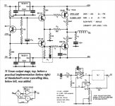
This circuit was proposed by K H Ellis in Electronics World "Circuit ideas" in December 1996 and then almost entirely quoted again by William de Bruyn in a short review of EC amps in the following June issue (a resistor seems to be missing between points P and R).
Has anybody tried it ?
As Ellis praised, any comments welcome.
Has anybody tried it ?
As Ellis praised, any comments welcome.
Attachments
This circuit was proposed by K H Ellis in Electronics World "Circuit ideas" in December 1996 and then almost entirely quoted again by William de Bruyn in a short review of EC amps in the following June issue (a resistor seems to be missing between points P and R).
Has anybody tried it ?
As Ellis praised, any comments welcome.
The idea is nice, but looking at the impedances around the ec circuit, it appears the author hasn't grasped the significant details
") .
.The way it is implementad it is an addition of both neg and pos feedback, but not in the correct proportions to qualify as Hawksford ec.
Do you have the full article, forr?
jd
The Ellis's article is very short. I'll send it to you.
Press ENTER to look up in Wiktionary or CTRL+ENTER to look up in Wikipedia
Merci beaucoup!
jd
Seems like a resistor from point P to R is missing. As it is the lousy version of feedback loop.
Yes that R is surely missing. But with 3.9K there, if you do the calculations for an Hawksford ec loop, he gets close, but not quite. I'm pretty sure that the adjustment pot is necessary to avoid instability, but it also destroys the error cancellation.
jd
Howdy,
there`s no need for that horrible "error canceling" circuit here. This output stage would produce less errors without the ICs and the other polluting parts.
Lumba,
Instead of showing everybody here that you are not up to speed on Hawksford error correction, you may want to read this:
http://www.essex.ac.uk/csee/researc...6 Distortion correction, power amplifiers.pdf
Then we can talk intelligently.
jd
Thank you, Jan. The substance of this paper is in harmony with my basic views. Things like the importance of wide bandwidth and the devastating impact of feedback from the output to the driving stages are pointed out. I`m still reading it.
Error feedforward (by H. Black, the inventor of negative feedback) offers some attractive features, such as a more extensive cancellation of residual distortions than negative feedback, no closed loop, no excess gain requirement, furthermore the main amplifier`s input is theoretically independent from the output. On the other hand, it requires matched components, the impedance seen by the error amplifier varies with signal amplitude and switching distortion may occur.
Quite a few proposals for error correction have been presented, but don`t expect any effortless practical implementation. Error correction circuits do harm as well, whereby the disadvantages can easily exceed the advantages. A careful functional and subjective performance evaluation is indispensable.
After properly assigned goals, a realization with discrete parts could be interesting. I strongly dislike the approach in post #1.
The CFP implies a mildly harmful error correction technique, working in a direct, efficient and precise manner.
- Status
- This old topic is closed. If you want to reopen this topic, contact a moderator using the "Report Post" button.
- Home
- Amplifiers
- Solid State
- Simple error correction amp ?