Can you guys and girls help me on this one?
I am looking to put together an audio mute switch that when inserted in a mono signal path will quietly mute the audio with out any pops, clicks or bangs and when switched out, will restore the audio without any noise also. I preferably would like the unit to be stand alone and so would need to run from say a 9v battery.
I checked this FET circuit here as it seemed ideal….
http://www.pic101.com/audiosw/index.html
I tried to model it in LTSpice and it seems to work but with a distortion figure well over 1% so I guess I may have down wrong. I am not sure if the circuit given is meant for a symmetrical power supply and therefore may not be of much use to me. I am also not 100% sure of the component values given (m,M etc) or how to config the circuit for a 9v supply. As I see it, no power is required unless the signal is muted, but I may be wrong!
Does anyone know of a suitable circuit for a mute switch. The main features would need to be…
1. Low distortion with line level signals up to around 2v pk
2. Quiet mute and restore
3. Low power consumption from a single 9v battery
4. Low impedance (signal to handle is in the range of a few hundred ohms)
Cheers
Ray
Hi,
you may want to look at using the FET as a shunt for the mute function.
That way the FET when near infinite impedance has least effect on the signal passing through. It's just it's capacitance that will affect the signal.
You can use a series FET and a shunt FET. that operate in opposite directions.
Find out what happens to a FET, whether in the series position or in the shunt position, when the AC signal is positive with respect to signal ground and when it is negative with respect to signal ground.
Hi Andy
Many thanks for your reply my man, appreciated. I was up your neck of the woods for the Oil & Gas exhibition in Aberdeen last week. Lovely part of the world Scotland!
Shunt made the best sense to me as you stated, this way the circuit should have minimum impact on the non muted signal. I tried this circuit here first …
http://www.circuit-projects.com/audio/soft-action-mute-switch.html
But no joy! I could not get enough attenuation on a low impedance signal. It states 10K to round 100K impedance signals, so this could be the reason. Again I could have implemented the circuit wrong in LTSpice for use with a 9v battery etc (bit of a dimmo I’m afraid!) It is a shame coz I liked the LED indication.
My knowledge of transistor basics is too sketchy to put to test with circuit configs and so that is why I have turned to the experts for help!!
Cheers
Ray
Hi,
to allow the shunt mute to attenuate, the source impedance must not be near zero.
If your source has a low impedance, say around 200r then the attenuation you will get in shunt mode will be low, i.e. a high volume will leak through.
You will need to add a series resistor between the input DC blocking cap and the FET. Try a 1k0 as a starter.

Andy
I tried the shunt circuit above with a 2.2K resister in series with the audio and it reduced the signal from 2.5 Vpk to 50 mV pk but the distortion was around 6% and over 2% with the signal at 1.0 Vpk. I am no expert at measuring distortion in LTSpice however and I just used the .FOUR 1k V(output) directive and read what was in the error log. Is this the right way to go about things?
Geek, do you have any circuits for using a Bi-Polar transistor for the mute as I *never* seem to have much luck with FET circuits with signals as high as 2.5v pk and using 9v batteries
Cheers
Ray
Here you go. Thinking about it a bit more as I was drawing it I think you don't need any extra resistors to get clean switching as the amps input will never have its input broken away from being able to source current.
Use a DPDT switch, the top half shown above is the normally closed ones and the bottom/right is the normally open ones.
The only downside to this is you would either need two switches or a quad gang one to switch stereo passively. If you used relays to switch the signal then you could still use the one switch but you would obviously then need a battery or power to run the unit.
An externally hosted image should be here but it was not working when we last tested it.
Use a DPDT switch, the top half shown above is the normally closed ones and the bottom/right is the normally open ones.
The only downside to this is you would either need two switches or a quad gang one to switch stereo passively. If you used relays to switch the signal then you could still use the one switch but you would obviously then need a battery or power to run the unit.
Cheers Richie!
Looks simple enough, I suppose the only thing to do is try it and see if it is quiet. The only downside is that I need the switch to be a foot operated device and DPDT seems quite rare in foot operated components, SPDT is the more common. My ideal would be a momentary action switch with the electronics providing the latch, but this would mean more complexity
Ray
Hi
Thanks for your replies. I would like if possible to reduce it to point where it couldn't be heard rather than just reduce the volume. Andy's idea of a small DPDT relay could be a good idea as I could aslo add an LED to indicate the swtiches state easily. I am just uncertain if the resistor switching can be relied on not to click or pop during switch in and out. I will need to try a few experiments to see.
Cheers
Ray
Geek, do you have any circuits for using a Bi-Polar transistor for the mute as I *never* seem to have much luck with FET circuits with signals as high as 2.5v pk and using 9v batteries
The one used by Yamaha for a decade was just a 4.7-10K resistor in series with the output, collector to that on the output side, emitter to ground, base to the controller chip through a little R-C circuit for shaping. There was no Vcc on the collector.
Tried it on a breadboard with a 2N5088 and worked well for line level mute
")
Cheers!
Thanks Geek
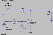
I tried this circuit attached based on a transistor I have knocking about and it seems to work quite well and I get at least -50dB reduction in volume. Is this what you mean?
The 2.2K series resistor is about as high as I want to go as I want to feed a 20K amplifier line input. Not sure if I have suitable values for the R-C components in the transistor base, or indeed if I have the R-C bit configured correctly. Can you experts give me any pointers here?
Cheers
Ray
Attachments
I am just uncertain if the resistor switching can be relied on not to click or pop during switch in and out. I will need to try a few experiments to see.
Cheers
Ray
The resistor is not switched in or out, the signal path is never broken, so there will be no pop or click.
Hi Ray,
You're welcome!
That's pretty much the circuit, yes.
Now that I see your base time constant circuit, that rings a big bell for values.
I recall a tuner w/muting using this circuit and was followed by an emitter follower so they could get away with higher levels of resistance in series. But it did have a little "thump" as it switched.
Maybe an opamp follower/linedriver (balanced for DC, hence no thump) if you want to get fancy?
Cheers!
Thanks Geek
I tried this circuit attached based on a transistor I have knocking about and it seems to work quite well and I get at least -50dB reduction in volume. Is this what you mean?
You're welcome!
That's pretty much the circuit, yes.
...Not sure if I have suitable values for the R-C components in the transistor base, or indeed if I have the R-C bit configured correctly. ..
Now that I see your base time constant circuit, that rings a big bell for values.
The 2.2K series resistor is about as high as I want to go as I want to feed a 20K amplifier line input.
I recall a tuner w/muting using this circuit and was followed by an emitter follower so they could get away with higher levels of resistance in series. But it did have a little "thump" as it switched.
Maybe an opamp follower/linedriver (balanced for DC, hence no thump) if you want to get fancy?
Cheers!
jFet as shunt switch
Old thread, but looking at the same subject
I'm working on a turn on / turn off circuit for Op-Amp's, working with a fet as a shunt switch on the op-amp's output
I want it to work on the regulated supply lines directly and not sensing on AC lines.
The output shut be shunted until the supply line has reached say 80%
At turn off is should react as fast as possible
Found a good inspiration here Class-A power amplifier project - Current-Drive - The Natural Way of Loudspeaker Operation ... and worked a bit further on it.
Not sure whether I need to do more with the gate circuit .... any ideas?
Guess j108 would be an ok choise for this application.
V2 simulates the negative supply line and V4 is the signal coming out of the op-amp
Any thoughts on this circuit??
Thanks in advance, Baldin
Attachments
- Status
- This old topic is closed. If you want to reopen this topic, contact a moderator using the "Report Post" button.
- Home
- Amplifiers
- Solid State
- Quiet Audio mute switch?