is this circuit a class-A PA?
http://img191.imageshack.us/img191/2549/classa.jpg
or a class-AB with a huge "Iq"?
or a class-AB with quasy-complementary?
someone say these circuit as 60W Class-A, will the output transistor survive?
what can i do to define between Class-A and class-B from the circuit?
thanx folks
http://img191.imageshack.us/img191/2549/classa.jpg
or a class-AB with a huge "Iq"?
or a class-AB with quasy-complementary?
someone say these circuit as 60W Class-A, will the output transistor survive?
what can i do to define between Class-A and class-B from the circuit?
thanx folks
Those diodes between driver's base set the bias.
they produce, together, 1.2 volts.... and this seems to be bias to be distributed between the drivers and output transistors.... seems to me, as have not resistance in series with the diodes to increase the voltage between bases that will operate in class AB or class B.
Class AB makes output transistors to conduct a very small current..so, into the emitter resistances you will be able to measure some milivolts developed while current is crossing the transistor junction.
When we ajust to class B, the output transistors does not conduct, but the voltage from base to emitter is not zero, the VBE into the output is around 400 milivolts or 350 milivolts, and this makes the output transistors be into the threshold of conduction...cutted, not conducting but waiting audio to increase the VBE and force them into conduction.
Class A is when you force a lot of current from colector to emitter... and this depends those diodes between base..increasing the number of diodes there you will have huge class A operation.
You output transistors are made to produce 10 watts of audio...maximum or 20 watts of audio...so..you cannot bias your amplifier to produce 60 watts or they will melt into the junction.
Maximum power cannot reach much more than 25 watts RMS into 8 ohms..and using those transistors you cannot use 4 ohms as you gonna burn the output.
regards,
Carlos
Attachments
Last edited:
This amplifier will sound fine..it is a bootstrapped one
and those sounds nice.
to the input use BC556 or BC546 depending if your input is PNP or NPN.
to VAS and drivers use BD139 and BD140 (NPN and PNP)
To output use 2SC5200 and 2SA1943 (NPN and PNP).
And be happy...with those ones..you can produce some mess and misadjustments....they will face the overload produced by some tweakings and may survive.
If you have intentions to build this one, well, seems that will work fine..but was not tested...we never know...i suggest you to search for proven circuits already build by several folks in this forum..a good one to try is P3A from Rodd Elliot and you can find it into ESP pages.
regards,
Carlos
Attachments
is this circuit a class-A PA?
http://img191.imageshack.us/img191/2549/classa.jpg
or a class-AB with a huge "Iq"?
or a class-AB with quasy-complementary?
someone say these circuit as 60W Class-A, will the output transistor survive?
what can i do to define between Class-A and class-B from the circuit?
thanx folks
Hello,
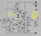
Because we have two diodes (D1 and D2), V_bias = ~ 0.65 * 2 = ~1.3 V and we can say that output transistors work in class B with I_bias roundness equal to 0. To function properly in class B or AB, we need a resistance (about roundness 20 Ohm) series with the two diodes.
Maximum power amplifier affected by value R13 = R14 = 1 ohm and the current through transistors TR6 and TR7 will be: I = 0.65 [V] / 1 [A] = 0.65 A. In considering the current and supply voltage of the amplifier, the amplifier power will not exceed 10W into 8 Ohms (min. 8 ohms).
Best Regards.
I will not build then
thanks alot Carlos, Donpetru, I will not build these thing then .
.
a few weeks ago I'm planning to build GC LM3886, but suddenly I've found those circuit, and someone who have it say it's a Class-A thing, (I would be pleased to build, while imagine the benefit of Class-A). I was surprised with those o/p Tr can it produce 60W? Class-A? what a disaster for the o/p Tr.
by the way, in Class-AB, if I just increase the Iq, the Class-A power will go higher right? says, from 100mA to 1,5A (somehow keep the temp remains warm). Which componen set the Iq (the series R in 2diode line?) and what the "side effect" of the increased Iq?
Is there any equation to determine the Iq rather than to measure the voltage on the emitter resistor?
btw, carlos, I think 2SC5200 not available in my region, it's a realy nice Power Tr from the specification, but maybe TIP3055/2955 fit the purpose (in 60W@4R) right?.
regards.
thanks alot Carlos, Donpetru, I will not build these thing then
.a few weeks ago I'm planning to build GC LM3886, but suddenly I've found those circuit, and someone who have it say it's a Class-A thing, (I would be pleased to build, while imagine the benefit of Class-A). I was surprised with those o/p Tr can it produce 60W? Class-A? what a disaster for the o/p Tr.
by the way, in Class-AB, if I just increase the Iq, the Class-A power will go higher right? says, from 100mA to 1,5A (somehow keep the temp remains warm). Which componen set the Iq (the series R in 2diode line?) and what the "side effect" of the increased Iq?
Is there any equation to determine the Iq rather than to measure the voltage on the emitter resistor?
btw, carlos, I think 2SC5200 not available in my region, it's a realy nice Power Tr from the specification, but maybe TIP3055/2955 fit the purpose (in 60W@4R) right?.
regards.
hi,
that is an old style quasi complimentary. you could make it high power pretty easily, but the circuit looks a little bit too outdated. better spending time on something with slightly better topology.
lots of writing on this page but the main schematic is a good example-
http://sound.westhost.com/project3a.htm
can omit br, sim1, sim2, not necessary. this type of design is relatively basic and solid.
Last edited:
if you want to still use the circuit, and you cannot get 2sc5200 etc.
tip41c & tip42c are fairly popular makes designed for general purpose power
amplifiers, or medium power linear applications.
they can handle 65w each, at 6A, 100V and have decent gain. TO-220 case.
keep them as cool as you can to keep them from power derating. will allow good power. just a decent heatsink. a reliable 40 watts or so per channel.
always welcome other ideas, this is just my quick one.
Hello,
Yes, the series R in 2 diode line can set the Iq.
Since, the maximum power transistors TR6 and TR7 is too small, this amplifier can't work in class A.
Again, as I said in another topic, to make such an amplifier in class A is not sufficient to increase Iq or bias current.
To polarize exactly a bipolar or MOS transistor in class A, must place the correct operating point of transistor to output characteristic (Iq = f (Uce)). This point (also called operating point class A) not regulates only with the Iq. Is need to respect the certain digram audio amplifier and certain characteristics and values of the electronic components of the diagram (this components need recalculate).
Regards
I've already a class-AB PA, quite similar with ESP P3A.
but I want to try something different (but not MOSFET nor Tube as they are expensive for me; a freelance at now) maybe the last PA project for a few year.
JLH 10W is realy nice, but its a little bit low power for me. DoZ is realy nice to, but I don't like a single supply as they need a coupling cap on its o/p.
Now, i think LM38x6 is the first prior.
thanx a lot folks, ;-)
Regards,
Maximum power amplifier affected by value R13 = R14 = 1 ohm and the current through transistors TR6 and TR7 will be: I = 0.65 [V] / 1 [A] = 0.65 A. In considering the current and supply voltage of the amplifier, the amplifier power will not exceed 10W into 8 Ohms (min. 8 ohms).
Best Regards.
where is the voltage (0.65V) come from?
and I = V/R, do you mean 1 [Ω], rather than 1[A]?
if I simply change the RE value with lower ones, will the PA max current increases? so do with the power (as P=V*I)?.
thx...
- Status
- This old topic is closed. If you want to reopen this topic, contact a moderator using the "Report Post" button.
- Home
- Amplifiers
- Solid State
- Is this a Class-A Circuit?