1.Use some wires to short the the 'X Y Z' terminals and power up.
If you can hear the sound of 7-9 times the relay operating, The mcu is ok.
2. Connect the device to PC by usb, open the device manager, if you can find the 'prolific usb to serial comm port(COM X), then the USB interface is OK。
3. run the software and goto options->config, click the 'auto detect and get parameter'.
if Curve Tracer is ok, it will display ‘parameter have get from Drvice’,
if will display ‘Device not found’. It may be the usb cable not good or another reason.
Hi locky, after many months of perfect performance I have an issue now unfortunately. I was measuring a number of n channel power mosfet and then suddenly I am having problems. Curve tracer gives no measurements anymore for n channel fet.
Xyz DUT autodetect is working ok. P-channel fet curve trace also working ok.
How do I fix this urgently ? Thanks !!
Xyz DUT autodetect is working ok. P-channel fet curve trace also working ok.
How do I fix this urgently ? Thanks !!
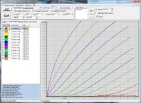
Measuring N type small currents is normal? For example NPN Hfe-Ic curve,(RC = 1K, RB=1360K or 91k).
If NPN Hfe-Ic curve,(RC = 1K, RB=1360K or 91k) is OK, but when select RC=68 the max Ic only about 30mA, You can observe the data in column of 'VE', In normaly the value in 'VE' is stabilized at 2.5V.
If the VE is increase, It maybe the PNP power transistor on E channle amplifier is wrong.
You also can save the curve data and snap the screen of measure condition and email to me(lockyz@yahoo.com).
")
Got the Curve Tracer board since a month, but only got time to try it today. When I curve traced a BF862, got the attached graph. The top curve (when Vgs=0) have a strange shape when Vds is between 2.5-4.5V, what could be causing that?
Attachments
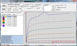
Oscillation may occur on DUT,
FET when you need to stay away from the circuit board, GATE is generally recommended series with a resistor in order to suppress oscillations.
The tracer B channel output pass through RB/ two relay to socket B.May be DUT oscillation.
Try connect a 100ohm resistor to the Gate and connect to B socket.
...Try connect a 100ohm resistor to the Gate and connect to B socket.
Thanks Locky, a gate stopper does solve the issue.
As I'm using a 40V/5A switching power supply, I have replaced the 2 LM358s with LT1013, and the curves become smoother afterwards. If I want to be able to measure current of up to 4A, what value of R50 would you recommend?
If I want to be able to measure current of up to 4A, what value of R50 would you recommend?
I'm not solder the 'protect sw' switch button. you can install these switch button.
When you want measure current more than 2.5A, you can hold down the switch button and begin measure.
This button temporary disable the over-current protect circuit.
I upload the software and document to yahoo group.Hi all:
Can u direct me to dl the s'ware for this tracer for win7/64?
https://uk.groups.yahoo.com/neo/groups/CurveTracer/info
You join the group and can find the software.
I am finally getting around to mounting my curve tracer in a box. I have a few questions:
1) I would also like to know what is the matching part number for the orange power connector on the board?
2)Can you please recommend a tact switch that fits the board holes for the" protect sw"?
3) According to my measurements some of the PCB mounting holes are connected to ground, some of them are connected to nothing and some seem to have an ohm or two resistance to ground. I am mounting the unit in a metal case. Should the mounting holes be electrically isolated from the case?
Thanks.
- Status
- This old topic is closed. If you want to reopen this topic, contact a moderator using the "Report Post" button.
- Home
- Amplifiers
- Solid State
- DIY Curve Tracer for PC