Thinking of purchasing one of these
guys I have never used a curve tracer but am a quick study! I have BP ouputs i want to match and some smaller driver and signal transistors....this should do the job...
the question is did anyone adapt to measure/match op amps? this would be very helpful for what i need to do..
Thanks
Lawrence
guys I have never used a curve tracer but am a quick study! I have BP ouputs i want to match and some smaller driver and signal transistors....this should do the job...
the question is did anyone adapt to measure/match op amps? this would be very helpful for what i need to do..
Thanks
Lawrence
What are you trying to match on opamps? While there are curve tracer methods for opamps you can do the same with a few simple test fixtures. A lot depends on what you want to know and what data sheet factor you want to check. Many datasheets, especially older ones include test circuits and that's a good starting point. You would need a good dual adjustable bench supply, a suitable signal source and whatever is appropriate for measuring the target parameter, a meter, oscilloscope or possibly distortion analyzer.
Probably the easiest and best would be the method on page 7 of this app note: http://www.ti.com/lit/ds/symlink/opa2604.pdf . What it does is reduce the available gain to drive the feedback network so the intrinsic distortion is reduced less by the feedback.
There are variations in the datasheets for other low distortion opamps. The distortion measured is directly proportional to the linearity.
Usually this turns out to be useful only for finding defective parts. Good IC's are really uniform making the whole effort tedious and somewhat pointless.
There are variations in the datasheets for other low distortion opamps. The distortion measured is directly proportional to the linearity.
Usually this turns out to be useful only for finding defective parts. Good IC's are really uniform making the whole effort tedious and somewhat pointless.
Lawrence,
You set the gain of a opamp by determining the feedback ratio. Accuracy is a function of the resistor ratio accuracy Usually you use 1% R's for this. For very precise ckts you use even higher precision R's, but they are not generally needed for audio work because 1% gain accuracy is more than enough for most audio ckts.
BTW, what do you not trust?
Linearity/distortion. You do not trust what TI specifies, good luck proving them wrong. I do not think that you can afford the equipment necessary to make a claim like that.
Rick
You set the gain of a opamp by determining the feedback ratio. Accuracy is a function of the resistor ratio accuracy Usually you use 1% R's for this. For very precise ckts you use even higher precision R's, but they are not generally needed for audio work because 1% gain accuracy is more than enough for most audio ckts.
BTW, what do you not trust?
Gain set by you R selection.to be honest I do not trust opamps
Linearity/distortion. You do not trust what TI specifies, good luck proving them wrong. I do not think that you can afford the equipment necessary to make a claim like that.
Rick
Its true that if you need either really precise gain (.0001% or better) or very large gain more that 120 dB the open loop gain will be an issue. It terms of nonlinearity the opamps of a given type will be very similar. These are usually controlled by passive R's and C's on the chip.
The manufacturing process is designed and optimized to yield really consistent parts. Most IC processes are more controlled than discrete parts. Any significant variations would make a part with 1 billion transistors impossible to make and Intel makes lots of them.
The manufacturing process is designed and optimized to yield really consistent parts. Most IC processes are more controlled than discrete parts. Any significant variations would make a part with 1 billion transistors impossible to make and Intel makes lots of them.
Here is a like to the manual for the TEK IC test fixture for their curve tracer http://www.ko4bb.com/Manuals/Tektro...inear_IC_Test_Fixture_Instructions_Manual.pdf It will give you lots of details and you may be able to make a clone enough to try it with Locky's curve tracer. If you do I'm sure others will be interested.
Yup. something hairy going on, looks to be noise, could be bad connections.
How do pnp bjt's measure?
Lawrence, I should apologize for this statement
As in traditional TI fashion, they removed the authors name from their updated app note, a shame really.
How do pnp bjt's measure?
Lawrence, I should apologize for this statement
After reading Bob Peace's article's, it would be interesting to test for opamp linearity, as he has done. Bob Pease was a magnificent contributor to electronics.Linearity/distortion. You do not trust what TI specifies, good luck proving them wrong. I do not think that you can afford the equipment necessary to make a claim like that.
As in traditional TI fashion, they removed the authors name from their updated app note, a shame really.
Last edited:
Yup. something hairy going on, looks to be noise, could be bad connections.
How do pnp bjt's measure?
Lawrence, I should apologize for this statement
After reading Bob Peace's article's, it would be interesting to test for opamp linearity, as he has done. Bob Pease was a magnificent contributor to electronics.
As in traditional TI fashion, they removed the authors name from their updated app note, a shame really.
its alright don't worry about it...I think its important to test all components in a piece of sensitive electronics including op amps etc..
Lawrence
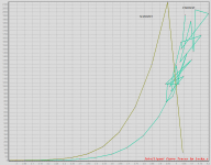
Try connect a 100ohm resistor between PMOS gate and socket B.But not without an issue appearing. my N MOSFET curve looks fine but my P MOSFET curve has issues. Any suggestions? Possibly a faulty relay?
expanding on this design
Hi locky_z,
Are you still working on your tester design or is it considered a finished product?
I started a new thread for something that is somewhat similar to your excellent design, although a little different:
http://www.diyaudio.com/forums/equipment-tools/249614-convenient-usb-based-transistor-tester.html
If you are open to expanding on your idea, perhaps you would participate in the design work on what I have proposed.
Curvetracer failed
Hi all:
I tried emailing locky Z yesterday but no reply yet. I have a curvetracer 3 months old...and the PC s'ware config 'device not detected' no longer detects it although the PL2303 port is detected and the curvetracer relays click once the USB is connected. I am using Com4 as the virtual port as indicated by the device manager, Win XP SP3. No yellow flagged driver probs.
Reinstalled the supplied PL2303 driver (2013) with no probs.
Any thoughts on what to do?
thx
Ancel
Last edited:
Intermittent
After removing the cover and measuring the key voltages, Vcc = 41, then 24, 12.16 and 5.1. Also tested the insulation of the transistors from the alum. sink which were ok. I tried it again and it started working.
So I don't know what it is yet, although the hand soldering job seems a bit poor.
Anyway I reassembled and it is still working for now.
Burnt out 2 small signal transistors by trying Hfe scripts w/o identifying if they were PNP or NPN. So the overcurrent LED works as well....
Auto tested a DUT to identify an NPN...works fine.. Did some HFe scripts on it...seems ok. Seems the Ic is measured in decimal mA....but volts are in V.
After removing the cover and measuring the key voltages, Vcc = 41, then 24, 12.16 and 5.1. Also tested the insulation of the transistors from the alum. sink which were ok. I tried it again and it started working.
So I don't know what it is yet, although the hand soldering job seems a bit poor.
Anyway I reassembled and it is still working for now.
Burnt out 2 small signal transistors by trying Hfe scripts w/o identifying if they were PNP or NPN. So the overcurrent LED works as well...
.Auto tested a DUT to identify an NPN...works fine.. Did some HFe scripts on it...seems ok. Seems the Ic is measured in decimal mA....but volts are in V.
- Status
- This old topic is closed. If you want to reopen this topic, contact a moderator using the "Report Post" button.
- Home
- Amplifiers
- Solid State
- DIY Curve Tracer for PC