The system can calculate the Yfs,
After you get the the Vgs-Id curve,
1. Hold down left mouse button, and draw a rectangle,
2. Release mouse button, then the menu will show,
3. Select 'Vgs=[xxx-xxx]Calculate(V)' menu
4. The system will use 'the method of least squares' to calculate the (delta)I/(delta)V, and show all curve value in the 'line slope' of column ,Their unit of measure is mA/V.
sweeping +Vc
Hi guys
I am trying to measure the simple IV characteristics of my solar cell in dark. I used a simple test diode before running measurements in my real device. I loaded the diode condition and tried a Vc sweep from -5 to +5 V with respect to the S/E and Vb = 0V. However the voltage does not sweep from +5V to -5V it only goes less than +1V (till +0.56). But the voltage does go to -5V. I am setting the current to be 300 mA so its not the case of reaching max current.
Please let me know what might be going on.
Thank you.
Hi guys
I loaded the diode condition and tried a Vc sweep from -5 to +5 V with respect to the S/E and Vb = 0V. However the voltage does not sweep from +5V to -5V it only goes less than +1V (till +0.56). But the voltage does go to -5V. I am setting the current to be 300 mA so its not the case of reaching max current.
Please let me know what might be going on.
Thank you.
"Vc sweep from -5 to +5V" is mean the power is from -5 to +5V,It include the voltage drop on Rc.
Attachments
Locky, I ordered the fully built box on eBay and got it a few days ago.
Installation went smoothly but I needed to reinstall the USB driver two times before the software would detect the tracer. Since then, I have played with it a lot this weekend and it is an excellent and useful tool to have.
I measured my first curve within 5 minutes of installing - your preset measuring setups make it easy for a beginner to get started.
I also LOVE the part and pin auto detect - makes life easier for us too lazy to check the datasheets. It autoidentified correcly all the semiconductors I tried except for the power jfet - but these are rare devices so thats not unusual I would imagine.
I think I'm only using 10 percent of what this device can do but further exploration is limited by the minimal English manual - wish I could read Chinese") maybe this is a useful reason to learn !
maybe this is a useful reason to learn !
Thank you for developing n supporting this very useful tool ! Cheers
Installation went smoothly but I needed to reinstall the USB driver two times before the software would detect the tracer. Since then, I have played with it a lot this weekend and it is an excellent and useful tool to have.
I measured my first curve within 5 minutes of installing - your preset measuring setups make it easy for a beginner to get started.
I also LOVE the part and pin auto detect - makes life easier for us too lazy to check the datasheets. It autoidentified correcly all the semiconductors I tried except for the power jfet - but these are rare devices so thats not unusual I would imagine.
I think I'm only using 10 percent of what this device can do but further exploration is limited by the minimal English manual - wish I could read Chinese
maybe this is a useful reason to learn ! Thank you for developing n supporting this very useful tool ! Cheers
Hi Locky,
I have unit 109, and I finally had the time to build in inside a nice enclosure, and now it is up and running fine. I started to do a lot of tests !
Now I have a key question (which I tried hard to answer myself), but I think there is something I don't understand, or something I do wrong.
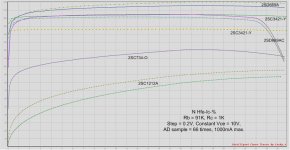
It's about the Hfe-Ic curve: what is the unit of Ic on the bottom curve line: mA or something else like x0.1 Amp?
To explain my question, see attached screendump with Hfe-IC curves for 2SC1212A, 2SC734-O, 2SC3421-Y, 2SD669AC and 2SD669A. The Ic measurements stop at 25~26 mA (?), while I expected the meter to go to 1000mA max as selected. I want to reproduce the same graphics as in the datasheets, where you can see when Hfe start to fall after 250~300mA (like the 2SD669AC curve in this picture, but it starts at 24 mA ???), but all the measurements stop at 25 mA ? (or is it 250mA?)
How can I make Ic to continue to where I want, say 500 mA? See also attached datasheets for the Hfe-Ic curves I want to reproduce.
thanks for the great tracer!!
I have unit 109, and I finally had the time to build in inside a nice enclosure, and now it is up and running fine. I started to do a lot of tests !
Now I have a key question (which I tried hard to answer myself), but I think there is something I don't understand, or something I do wrong.
It's about the Hfe-Ic curve: what is the unit of Ic on the bottom curve line: mA or something else like x0.1 Amp?
To explain my question, see attached screendump with Hfe-IC curves for 2SC1212A, 2SC734-O, 2SC3421-Y, 2SD669AC and 2SD669A. The Ic measurements stop at 25~26 mA (?), while I expected the meter to go to 1000mA max as selected. I want to reproduce the same graphics as in the datasheets, where you can see when Hfe start to fall after 250~300mA (like the 2SD669AC curve in this picture, but it starts at 24 mA ???), but all the measurements stop at 25 mA ? (or is it 250mA?)
How can I make Ic to continue to where I want, say 500 mA? See also attached datasheets for the Hfe-Ic curves I want to reproduce.
thanks for the great tracer!!
Attachments
Last edited:
Hi Locky,
I have unit 109, and I finally had the time to build in inside a nice enclosure, and now it is up and running fine. I started to do a lot of tests !
Now I have a key question (which I tried hard to answer myself), but I think there is something I don't understand, or something I do wrong.
It's about the Hfe-Ic curve: what is the unit of Ic on the bottom curve line: mA or something else like x0.1 Amp?
To explain my question, see attached screendump with Hfe-IC curves for 2SC1212A, 2SC734-O, 2SC3421-Y, 2SD669AC and 2SD669A. The Ic measurements stop at 25~26 mA (?), while I expected the meter to go to 1000mA max as selected. I want to reproduce the same graphics as in the datasheets, where you can see when Hfe start to fall after 250~300mA (like the 2SD669AC curve in this picture, but it starts at 24 mA ???), but all the measurements stop at 25 mA ? (or is it 250mA?)
How can I make Ic to continue to where I want, say 500 mA? See also attached datasheets for the Hfe-Ic curves I want to reproduce.
thanks for the great tracer!!
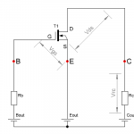
You can look the NMOS measure figure example.
You use RC=1K, and set 'Vce' constant at 10V.
When 'Ic'=25mA,then The voltage drop('Vrc') on RC is 25V.
Because C channel output maximum 36V(Power supply is 39V), So the more 'Ic', the smaller 'Vce'.
Attachments
Hi locky,
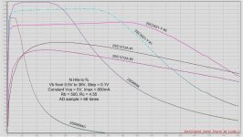
Thanks for the reply. yes, I could (should) have figured that myself . I tried many different settings and got very bad curves, but now I got the feeling of tuning and it all works fine. See new curves attached.
Finally I can start testing to find new modern transistors which are close to old transistors in 70's amplifiers. The curve below is just playing, but the example search is to find modern substitutes for the 2SC1212A (driver transistors for a 1975 Kenwood amp). The Japanese transistor manual (2009) says 2SC3421, and of course the good old 22D669 comes to mind (or BD137/139). The 2SC3421 comes in Y and O ranking (I got Y rank), hence I can now check if the O ranking (lower Hfe) is the one to get. The 2SD699 is not as good, and comes in so many different ranks, as this test shows (AC rank = crap, or I got counterfeits ?).
Super tracer !
And the 2SC3421 seems to be a VERY linear device.... very interesting....
Thanks for the reply. yes, I could (should) have figured that myself
. I tried many different settings and got very bad curves, but now I got the feeling of tuning and it all works fine. See new curves attached. Finally I can start testing to find new modern transistors which are close to old transistors in 70's amplifiers. The curve below is just playing, but the example search is to find modern substitutes for the 2SC1212A (driver transistors for a 1975 Kenwood amp). The Japanese transistor manual (2009) says 2SC3421, and of course the good old 22D669 comes to mind (or BD137/139). The 2SC3421 comes in Y and O ranking (I got Y rank), hence I can now check if the O ranking (lower Hfe) is the one to get. The 2SD699 is not as good, and comes in so many different ranks, as this test shows (AC rank = crap, or I got counterfeits ?).
Super tracer !
And the 2SC3421 seems to be a VERY linear device.... very interesting....
Attachments
The minimum resolution of the voltage of the tracers is probably about 2 mV.
If your current is less than 10mA, then the best choice for RC = 1K, Because the voltage drop on the RC can reach 10V.If you choose RC = 4.55ohm,the voltage drop on the RC only 50mV. Measure 50mV error is far greater than 10V.
So I suggest when you want to measure some transistor.
First: The collect current determines the range of the RC, How to determines the RC range? As much as possible the voltage drop on RC exceeds 0.5V.
Secondly: Assume the transistor hfe is 100, and calculate the base current, and base on the base current determines the range of RB,As much as possible the voltage drop on RB exceeds 0.5V.
Hi Locky_z
I am interested in getting one of your nice intelligent curve tracer in eBay.
What kind of computer have I to have here in order to run the software that you provide ? Does it run on Windows XP and Windows X7 ? Sorry for so a stupid question, but I prefer to ask before buying it.
Thank you for your answer.
Best regards
rephil
I am interested
in getting one of your nice intelligent curve tracer in eBay.What kind of computer have I to have here in order to run the software that you provide ? Does it run on Windows XP and Windows X7 ? Sorry
for so a stupid question, but I prefer to ask before buying it.Thank you for your answer.
Best regards
rephil
Dunno abt the 2sc3421 but how did you get the text and labels on the graphs ? Mine is a rats nest and I'm dyin to figure how to label the individual traces on the graph ....Hi locky,
Thanks for the reply. yes, I could (should) have figured that myself
Finally I can start testing to find new modern transistors which are close to old transistors in 70's amplifiers. The curve below is just playing, but the example search is to find modern substitutes for the 2SC1212A (driver transistors for a 1975 Kenwood amp). The Japanese transistor manual (2009) says 2SC3421, and of course the good old 22D669 comes to mind (or BD137/139). The 2SC3421 comes in Y and O ranking (I got Y rank), hence I can now check if the O ranking (lower Hfe) is the one to get. The 2SD699 is not as good, and comes in so many different ranks, as this test shows (AC rank = crap, or I got counterfeits ?).
Super tracer !
And the 2SC3421 seems to be a VERY linear device.... very interesting....
Hi Locky_z
I am interested
What kind of computer have I to have here in order to run the software that you provide ? Does it run on Windows XP and Windows X7 ?
rephil
I have test it under winxp 32bit / Win7 32bit /Win2008 64 bit server, They run all well.
But someone say the USB drivers(PL2303 chips) under win8 is not compatible.But someone say use the pl2303 drivers Version 1.5.8 or more earlier is OK.
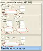
The figure show how to display the axis-label.Dunno abt the 2sc3421 but how did you get the text and labels on the graphs ? Mine is a rats nest and I'm dyin to figure how to label the individual traces on the graph ....
But the curve label can not display,You can move the mouse over the curve, the curve name will display on status bar.
Attachments
Dunno abt the 2sc3421 but how did you get the text and labels on the graphs ? Mine is a rats nest and I'm dyin to figure how to label the individual traces on the graph ....
Simple.... copy graphic to clipboard, paste in MS Visio, add text boxes (rotate and format text as required), select all and copy to clipboard (CTRL-A and CTRL-C), then paste in IrfanView (or similar graphic viewer) and safe it as JPG file.
I have test it under winxp 32bit / Win7 32bit /Win2008 64 bit server, They run all well.
But someone say the USB drivers(PL2303 chips) under win8 is not compatible.But someone say use the pl2303 drivers Version 1.5.8 or more earlier is OK.
I confirm mine is working under Win7 64 bit, but I do get an occasional error message (1 out 25 times) that the COM link is not working when I hit the 'GO' button, but clicking 'GO' again solves that problem. Seems like a timing/synchronisation problem on the comm link, not an issue with the comm driver/protocol
I confirm mine is working under Win7 64 bit, but I do get an occasional error message (1 out 25 times) that the COM link is not working when I hit the 'GO' button, but clicking 'GO' again solves that problem. Seems like a timing/synchronisation problem on the comm link, not an issue with the comm driver/protocol
Thank you for this help Amplifire
as I have the Win 7 64 bit too and also the Win XP 32 bit on a slow, old and tired computer that is going away.Best regards
rephil
- Status
- This old topic is closed. If you want to reopen this topic, contact a moderator using the "Report Post" button.
- Home
- Amplifiers
- Solid State
- DIY Curve Tracer for PC