It seem that the system try to keep 'Vce' fixed,but do not well.
The system keep Vce fixed is use software feedback.
Example measure p type, VCE fix at 15V and Vgs step up to 2.6V.
The process step is:
1.System will set E channel output 36V,B output 36-2.6=33.4V
2.System set C channel output 36-15=21V,
3.Measure the Vce, example Vce is 0.5V,
4.Compare the measure Vce(0.5V) and VCE(15V), The difference is -14.5V,so system adjust the C channel output to 21+(-14.5)=6.5V,
5.Measure the Vce again,and adjust C channel output
6.Until 10 loops or Vce-VCE less 50mV.
At step 4,5 ,system increase the C channel output, and the current also grow, and the VE may change, so It may reduce a little adjust.may make system hard to keep Vce fixed.
And you use LT1013 replace LM358,Its gain is better than LM358,It keep VE stabel better than LM358.
You change the parameter 'Options->Config->Voltage drop(Source)' to 3V, and try again,
Or
Try to load 'Vgs-Id(No Fix Vce)' . This measure condition is Set C channel to max output voltage, It mean Vrc(the voltage drop of RC) + Vce is fixed. It no longer adjust Vce,the curve may more smooth.
But the Vce of every point on curve is difference.
I think I have a problem mesuring HFe for BC327 40 and BC337 40
HFe range for those is up to 630
The transistors are from Fairchild direct so no fakes
The PNP I have tried so far all mesure HFe much larger than transistor specification
of the first 100 measured are all above HFe 600 and up to 720
Can msure of PNP mesure be out of calibration?
HFe range for those is up to 630
The transistors are from Fairchild direct so no fakes
The PNP I have tried so far all mesure HFe much larger than transistor specification
of the first 100 measured are all above HFe 600 and up to 720
Can msure of PNP mesure be out of calibration?
Each hfe-Ic curve at the beginning part, is not accurate enough.
Because the current is very small, The voltage drop on the RC RB is small, System measure them not accurate. So Hfe=Ic/Ib is vary greatly.
From the data,you can get the IC and Ib , and you use Vrc=Ic*RC,Vrb=Ib*RB to calculate VRC,VRB.
If Vrc & Vrb is samll than 0.25V,means they may not accurate enough. I suggest discard them.
Tanks locky_z
I have set up
mesure form 0.5v to 10 0.5 step fixed VCE 10 V current max 800 mA
all NPN mesure in range all PNP are 60 or more over spec
Ofset on PNP does not make sense
When I mesure with Atlas component tester mesure is different and PNP are ok
If not acurate it is ok as long as this is constant
Will try to post curves later
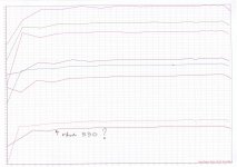
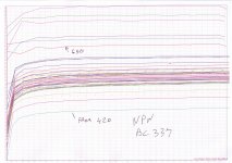
Here are curve from BC337-40 NPN and BC327-40 PNP
PNP mesure is wrong, very hi HFE
Transistors are original Fairchild from manufacturer
I have mesured 400 PNP and 1000 NPN
NPN ok PNP vrong go up to 770 big offset
I don't understand why?
When I mesure with Atlas component tester PNP HFe is ok and same as NPN
PNP mesure is wrong, very hi HFE
Transistors are original Fairchild from manufacturer
I have mesured 400 PNP and 1000 NPN
NPN ok PNP vrong go up to 770 big offset
I don't understand why?
When I mesure with Atlas component tester PNP HFe is ok and same as NPN
Attachments
When Ic is less 0.5mA,The Ib is less than 0.5mA/Hfe=0.5/700=700nA,
The buffer(OP07) bias current is 1.2nA,offset current is 0.5nA, they all less than the Ib, So the system measure the Ib is right,
So I think the pnp curve is right. Its Hfe is more than 700.
I look at your picture,The Ic is less 1.8mA, I suggest use RC=12K,
When ic less 0.5mA, the Vrc=0.5*12K=6V,
If you use RC=1K, the Vrc only 0.5*1K=0.5V,
System measure the small voltage may have less 15mV error.So if use RC=12K is better than RC=1K
Tanks locky I will try with 12 K still PNP mesure different from NPN.
Error shuld be same if there is error.
When I mesure with different instrument HFe is as on data sheet.
Data sheet say HFe is between 400 and 630 for both transistors
Many NPN mesure at around 520
PNP around 640 if I change formulae to Hfe=abs(Ic/Ib)-120 then HFe is ok
I do not understand why ?
Error shuld be same if there is error.
When I mesure with different instrument HFe is as on data sheet.
Data sheet say HFe is between 400 and 630 for both transistors
Many NPN mesure at around 520
PNP around 640 if I change formulae to Hfe=abs(Ic/Ib)-120 then HFe is ok
I do not understand why ?
Their no polarity inverter circuit,
The PNP measure diagram is below
 、
、
If test PNP, System will set Eout to 36V,
And step down the Bout inorder to generate Ib.
System measure the Vrb,Vrc and calculate the Ic and Ib and Hfe.
The Vrb Vrc measure circuit is below
It use a OP07 as follower, The op07 bias current and offset current will have some voltage drop on RB. But Op07 bias current and offset current less 5nA,and Op07 offset voltage is less 1mV,so OP07 only a little affect to DTU base current.
The PNP measure diagram is below
If test PNP, System will set Eout to 36V,
And step down the Bout inorder to generate Ib.
System measure the Vrb,Vrc and calculate the Ic and Ib and Hfe.
The Vrb Vrc measure circuit is below
It use a OP07 as follower, The op07 bias current and offset current will have some voltage drop on RB. But Op07 bias current and offset current less 5nA,and Op07 offset voltage is less 1mV,so OP07 only a little affect to DTU base current.
Attachments
Softwere update ,It can support script control.
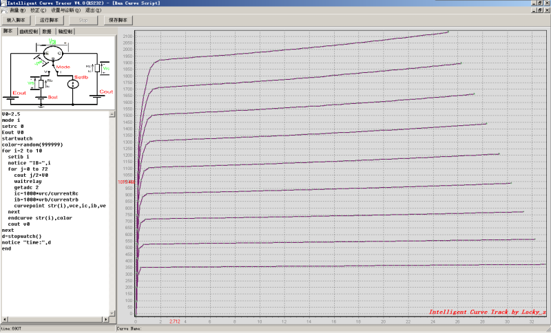
The script is
V0=2.5
mode i
setrc 0
Eout V0
startwatch
color=random(999999)
for i=2 to 10
setib i
notice "IB=",i
for j=0 to 72
cout j/2+V0
waitrelay
getadc 2
ic=1000*vrc/currentRc
ib=1000*vrb/currentrb
curvepoint str(i),vce,ic,ib,ve
next
endcurve str(i),color
cout v0
next
d=stopwatch()
notice "time:",d
end
The software link
http://www.diyaudio.com/forums/atta...t-curve-tracer-3-0-release-ads7871_script.zip
software update 2012.7.13
Bug fix:
1.if use negative parameter in setIb ,It have error.
2.add initialization currentRB,currentRC variables when press ‘run' button.
http://www.diyaudio.com/forums/atta...t-curve-tracer-3-0-release-ads7871_script.zip
Bug fix:
1.if use negative parameter in setIb ,It have error.
2.add initialization currentRB,currentRC variables when press ‘run' button.
http://www.diyaudio.com/forums/atta...t-curve-tracer-3-0-release-ads7871_script.zip

Stefano,
See the link to eBay in Locky_Z signature
locky_z's Intelligent curve tracer | eBay
Intelligent curve tracer main board | eBay
Fred
See the link to eBay in Locky_Z signature
locky_z's Intelligent curve tracer | eBay
Intelligent curve tracer main board | eBay
Fred
I wrote a component of the Tracer installation/ calibration/ diagnostic manual in chinese,
Who can help translate into English.
I more than happy to help with tidy up of this but not good enough to start from scratch.
Your English is not to bad and if you get started we can get there...
- Status
- This old topic is closed. If you want to reopen this topic, contact a moderator using the "Report Post" button.
- Home
- Amplifiers
- Solid State
- DIY Curve Tracer for PC