Just received my Curve Tracer. All looks well, but I have two questions:
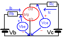
1)My board is missing the capacitor in the lower left of the drawing above, that was prone to being leaky. I assume it was found not to be necessary at all. Is that true? Or should I add one back?
2) What are the X,Y and Z terminals for?
Thanks
Terry
1)My board is missing the capacitor in the lower left of the drawing above, that was prone to being leaky. I assume it was found not to be necessary at all. Is that true? Or should I add one back?
2) What are the X,Y and Z terminals for?
Thanks
Terry
I will let Locky_Z answer to your first question...
X, Y, and Z terminals are for detecting an unknown device type.
Just put a 3 legged device in X, Y, and Z and the software will tell you what type it is (BJT, JFET, etc...) and what pin X, Y, and Z correspond to.
This is the "DUT Auto Detect" function of the software
It also works for 2 legged devices such as diodes or zener...
Fred
Thanks Fred. I guess if I had read the documentation more closely I would have known that. Still, it is a very cool feature. I knew it was there-but now I know how to use it!I will let Locky_Z answer to your first question...
X, Y, and Z terminals are for detecting an unknown device type.
Just put a 3 legged device in X, Y, and Z and the software will tell you what type it is (BJT, JFET, etc...) and what pin X, Y, and Z correspond to.
This is the "DUT Auto Detect" function of the software
It also works for 2 legged devices such as diodes or zener...
Fred
The capacitance in red circle is 24V Filter capacitor, they areI in parallel, so install a capacitance is enough.Just received my Curve Tracer. All looks well, but I have two questions:
1)My board is missing the capacitor in the lower left of the drawing above, that was prone to being leaky. I assume it was found not to be necessary at all. Is that true? Or should I add one back?
Terry
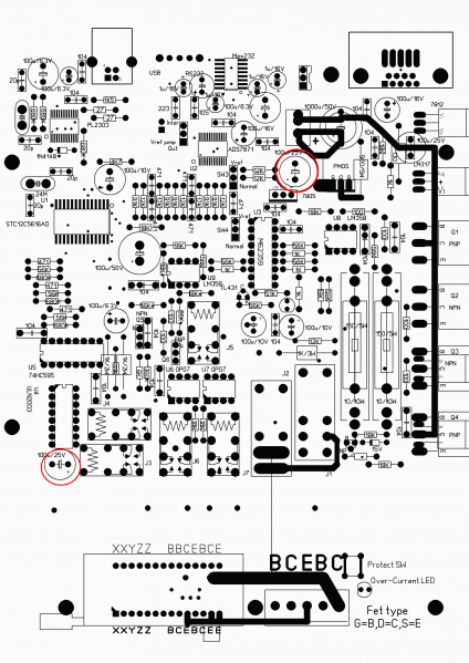
Thanks for the quick feedback.The capacitance in red circle is 24V Filter capacitor, they areI in parallel, so install a capacitance is enough.
One more question. While I have a connector for the power supply input that will fit, could you provide the part number for the unit connector on the board. I would like to find the appropriate mating plug since the connector seems to be 'polarized' and I would like to prevent myself from plugging the power in backwards.
Thanks again.
Thanks again.
and I would like to prevent myself from plugging the power in backwards.
Wise precaution !

Hi locky_z
I want to thank you for making this very useful tool, at an affordable price.
And thanks to Fred for organising the GB.
Agree with Bksabath. Best money ever spent.
I have used a 33V AC, 200VA transformer saved from a broken labsupply, and regulated it down to 31V DC with a simple zener + power darligton sceme.
There is one issue however:
In the dropdown menu for RC the choises are: 1K, 75, 1K, 12K.
If I choose the top 1K were the 4R7 choise would be I get a very low reading.
I have taken some Oscope shots from collector to ground with corresponding curves for different settings, on the same powertransistor. (2SC 3281)
VB 0.5 to 30V, 0.5V step. Constant VCE 30V. Imax 2500 mA.
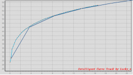
1 and 2, RB 6K RC 75
3 and 4, RB 91K RC 1K
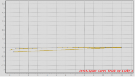
5 and 6, RB 500 RC 4.7 ?
I would be very happy if there is a way to fix this.
Please let me know if there are any other measurements you need to diagnose whats wrong.
I want to thank you for making this very useful tool, at an affordable price.
And thanks to Fred for organising the GB.
Agree with Bksabath. Best money ever spent.
I have used a 33V AC, 200VA transformer saved from a broken labsupply, and regulated it down to 31V DC with a simple zener + power darligton sceme.
There is one issue however:
In the dropdown menu for RC the choises are: 1K, 75, 1K, 12K.
If I choose the top 1K were the 4R7 choise would be I get a very low reading.
I have taken some Oscope shots from collector to ground with corresponding curves for different settings, on the same powertransistor. (2SC 3281)
VB 0.5 to 30V, 0.5V step. Constant VCE 30V. Imax 2500 mA.
1 and 2, RB 6K RC 75
3 and 4, RB 91K RC 1K
5 and 6, RB 500 RC 4.7 ?
I would be very happy if there is a way to fix this.
Please let me know if there are any other measurements you need to diagnose whats wrong.
Attachments
-
 CT Test RB 6K RC 75R.png16.3 KB · Views: 485
 -
 CT Test RB 6K RC 75R Oscop.png19.9 KB · Views: 482
 -
 CT Test RB 91K RC 1K zoom.png17.7 KB · Views: 481
 -
 CT Test RB 91K RC 1K Oscop.png19.7 KB · Views: 90
 -
 CT Test RB 500R RC 4R7 zoom.png14.6 KB · Views: 163
 -
 CT Test RB 500R RC 4R7 Oscop.png19.9 KB · Views: 76
Last edited:
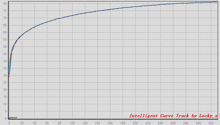
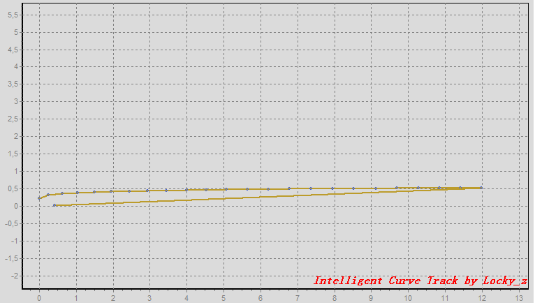
Your measure condition is 'VB 0.5 to 30V, 0.5V step. Constant VCE 30V. RB=6K Rc=75'
From the following diagram
Vb from 0.5 to 30V, RB=6K,mean Ib is from 0 to (30-0.65)/6K=4.89mA,
if Hfe is 70,then Ic is from 0 to 342mA,
then the voltage drop at RC=75(Vrc) is 0 to 25.67V
because Vce+Vrc+5V must <= supply voltage, but your supply only 31V,
When Ic increases,Vrc increases, the Vce can not constabt at 30V.
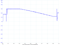
you see this picture
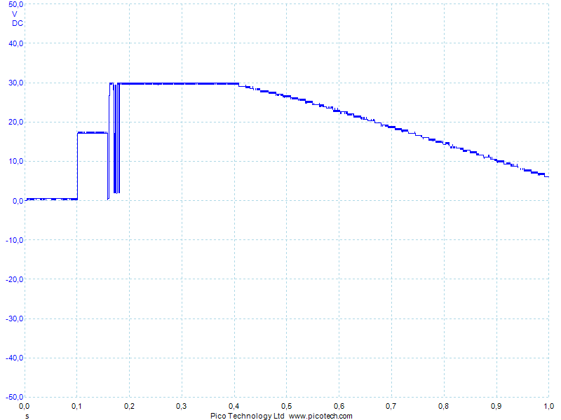
A start can be maintained in the 30V, but as the current increases, the increase of Vrc, Vce won't stay, you will see the Vc drop.

the same RB=91K RC=1K,you can calcuate the Ib and Vrc drop range,
RB=500 RC=4.55
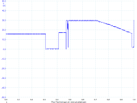
trhis picture I don't know why
Thank you for answering locky_z.
The Oscope grafs was added to show that there is some measuring going on in all 3 settings.
I set the supply voltage so low because the opamp max voltage mentioned by Fred, just to be on the safe side.
The two first Curve tracer grafs looks reasonabl I think, but the third one seems too come out wrong. The same thing happens when I set VB 0.5 to 5V, constant VCE 10V.
A tiny graf at the left bottom corner.
I suspect there is something with software or calibration because the dropdownbox for
RC is from top to bottom:
1K
75
1K
12K
I think it measures what it should, but something in the calculation prosess goes wrong.
When RC is 4.55 and the software calculates from voltage drop as if RC is 1K I think the graf would be something like the third one.
I have Unit 127, if you have the files for different units saved.
The little configfile you open in notepad says RC0=4.55......
Regards Styrk
Last edited:
In the calibration meny under current calibration it says RC0=1K
Maybe something there is wrong here, but I cant chance the values so I dont know what to do here.
Styrk
You select menu Options->Config,
select page 'Relay and resistor define',
If RC0 's value not '4.55' ohm,you can change it to '4.55' and save.
Note: Because float display problem, 4.55 may display as 4.55000019073486.
Hi locky_z,
I had the same issue as styrkv.
It has to do with the decimal separator. In many countries, it isn't a point but a comma. When first running the soft, the select box for Rc value of 4.55R appeared as 1K and the Constant Ib courrent feature didn't work, no base current was flowing at all.
To overcome this, I just replaced all the decimal points by a comma in the S7871_V3S.ini file.
I also got some inconsistent results from time to time. The schematic and the static measure feature were very helpfull to discover what was going on. Without any device inserted, VB was sometimes higher in value that VBH. I discovered a bad solder joint on the normaly closed contact of J6.
It's now working well and I must thank you Locky for this very powerfull and simple to use tool. For sure like pointed earlier, a best buy.
Francis
thank your replyHi locky_z,
I had the same issue as styrkv.
It has to do with the decimal separator. In many countries, it isn't a point but a comma. When first running the soft, the select box for Rc value of 4.55R appeared as 1K and the Constant Ib courrent feature didn't work, no base current was flowing at all.
To overcome this, I just replaced all the decimal points by a comma in the S7871_V3S.ini file.
Francis
Locky_Z
I'm very happy with your curve tracer, still learning but i noticed that the big relays (J1 and J2 ) get very warm...is this normal ?
'The big relays (J1 and J2 ) get very warm' is normal.
The relay coil resistor is about 1K, so under 24V supply,It will consume 0.5W.
You can change LM317 output voltage, reduce 24V to 20V,because relay can also work in 20V.
24V power supply is only available to the relay power, and followed after 7812, a 12V power supply to the DAC.
Therefore, 24V reduced to 20V, will not impact on 7812.
Fellow DIY'er,
I'm a newbie to curve tracing and I would like your help using this device. I can happily report that it seems to respond properly right out of the box! Thanks.
I would like to match 2SK170-BL devices (and 2SJ74-BL later on) using this instrument.
What settings should I use?
There are an overwhelming number of options and I really do not know where to start.
As many of us are using 2SK170's in our gear, and as several of us have or will have this curve tracer, I think it might be a good idea to use the same parameters.
Any help would be greatly appreciated!
Cheers,
Nic
- Status
- This old topic is closed. If you want to reopen this topic, contact a moderator using the "Report Post" button.
- Home
- Amplifiers
- Solid State
- DIY Curve Tracer for PC