I need much help with this now
Board is working but I have problem with mesure
I like to mesure Mosfets for matching VGS ( N type FQP19N20 and P FQA12P20)
I think I need to mesure current at a variable VGS
I have Variable VB = from 0 to 6 volts
Constant VCe =20V
Imax2000 mA
When I mesure ID I think is wrong (most probably my mistake)
Help please
Attachments
OKEY DOKEY
Got it
there is a limited numbers of calculation made using parameters
Load N Vgs->Id-%
Highlit expression and clik edit
Change Name to one of your choice
then change expression on left axis to =Ic
Swap the expression on X=
with one on Y= and repeat top to botom botom to top.
Test your mosfet
Now curve will show Vgs agains Id
Graph flatens out once you hit the current limit (2500 mA )
so no worries there
Absolutley briliant
Lcky-Z
your curve tracer is realy good tanks for making it
I hope You will make more and better (more voltagge and current)
PS If this unit can be modified for more Voltagge and Current let me know please)
Lazy Butt
Realy tank you wery much for making this possible.
Now proper show of gratitude well due
Bit of back ground
I was matching FQP19N20 for my F5
I use 24 V 2A and constant themperature of 50 C (this takes loads of time and fine calibration to get thigs right and constannt results)
I have made same mesurament using same pre sorted, with above method, mosfet
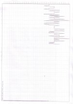
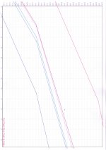
Graph show the 6 curves of 2 controll devices and 2 pairs
The curve tracer confirm the results I was gettin before
Graph one and Zoom in.
Best money I have ever spent IMO
PS Am I the only one to get this working so far?
(some how I dont think so)
your curve tracer is realy good tanks for making it
I hope You will make more and better (more voltagge and current)
PS If this unit can be modified for more Voltagge and Current let me know please)
Lazy Butt
Realy tank you wery much for making this possible.
Now proper show of gratitude well due
Bit of back ground
I was matching FQP19N20 for my F5
I use 24 V 2A and constant themperature of 50 C (this takes loads of time and fine calibration to get thigs right and constannt results)
I have made same mesurament using same pre sorted, with above method, mosfet
Graph show the 6 curves of 2 controll devices and 2 pairs
The curve tracer confirm the results I was gettin before
Graph one and Zoom in.
Best money I have ever spent IMO
PS Am I the only one to get this working so far?
(some how I dont think so)
Attachments
Last edited:
Hi
I think you are the only one got the first set. I am still waiting because of the shipping from Europe.
It will be a good idea if you can post some sort of user manual , how to do it right or what might be useful first steps
I am planning on using it for Small signal FETs when it arrives
I think you are the only one got the first set. I am still waiting because of the shipping from Europe.
It will be a good idea if you can post some sort of user manual , how to do it right or what might be useful first steps
I am planning on using it for Small signal FETs when it arrives
Shipping from Europe? So it is shipped from China -> Europe -> US?Hi
I think you are the only one got the first set. I am still waiting because of the shipping from Europe.
It will be a good idea if you can post some sort of user manual , how to do it right or what might be useful first steps
I am planning on using it for Small signal FETs when it arrives
Lazy-Butt had a few ( 3 units) to post on his trip back to France
maybe thats why I got there this early
I am shure the rest be there soon.
I got really surprised on how easy it is first of all to install and then use
Don't know about how to do it right part.
I am shure there are better qualified people out there but shure why not
You got guide on how to test N mosfets already.
From what I have saw to set up the formulae you folow more or less same guidelines as one would do for Excell.
No problem messing things up as is on the CD
And if it stop responding (this was my fault unplughed/ plughed cable ) Just reload and run the configuration again.
(May save you 3 minutes of panic panic )
It would be great that Locky_z had a go first and then we can all chip in and translate.
So I would say fire up questions and see
Not that I had much trubles understanding what is already in the manual.
I think I said this alredy the best money I have ever spent.
Shipping from Europe? So it is shipped from China -> Europe -> US?
Yep, as Bksabath said, I was on business trip last week, so a few lucky ones got it shipped from France and got it faster (and cheaper).
All curve tracers from now on will be shipped from China as I have no plans to return to Europe any time soon..... BTW... next batch will be shipped this weekend... I'll contact you guys for payment (around ~8 units this week)
Fred
Hi
I think you are the only one got the first set. I am still waiting because of the shipping from Europe.
It will be a good idea if you can post some sort of user manual , how to do it right or what might be useful first steps
I am planning on using it for Small signal FETs when it arrives
Kannan,
I put a link to download the user manual in the GB thread (2nd and 3rd posts). For me it was enough to get me started and trace some curves almost straight out of the box.
I think I said this alredy the best money I have ever spent.
Geez thanks ! that is heart warming.. makes me think the GB was well worth the effort.
That being said, the biggest credit should go to Locky_z for developing such a good device and software !!
") . It looks great, but sadly I am not able to use it until next weekend, there really is no time available
. It looks great, but sadly I am not able to use it until next weekend, there really is no time available For those who purchased this fantastic device, here are a few useful info from Locky_z:
1- Power voltage:
The specification from Locky_z is 32-40V DC @ 2.5A
There was some concerns raised by one of the GB subscriber that one of the OpAmp : the LM358 is spec'ed at 32V max. The unit has been tested up to more than 40V, without any problem whatsoever, and the OpAmp probably has some safety margin.
=> For those who are concerned, it is preferrable to power the unit @ 32V maximum, or to change the OpAmp for a higher voltage OpAMp such as the LT1013.
This OpAmp only controls the relays and can be changed without any effect on the calibration
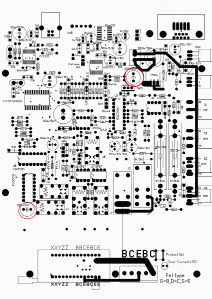
2- Leaky capacitors
This week, Locky_Z discovered that a few of his capacitors stock were leaky. The capacitors concerned are the ones in the 100uF@25V position as in the picture below. Faulty ones are blue colored 330uF/25V branded YEELEE. (if yours are from a different model or brand, then you should be fine)
Although all units shipped were tested by Locky_z, and checked by myself prior to shipment, it is still recommended to change these caps as a precautionary measure. Any good quality caps will do, but it is recommended to change to 35V rated ones
All units shipped from now on will be exempt of the issue.
Don't hesitate to post here if you have any question or comments. I know Locky_z is reading the thread regularly, and I can also transfer to him in case there are language issues. Surely there are also knowledgeable members here who will be able to help!
Cheers
Fred
1- Power voltage:
The specification from Locky_z is 32-40V DC @ 2.5A
There was some concerns raised by one of the GB subscriber that one of the OpAmp : the LM358 is spec'ed at 32V max. The unit has been tested up to more than 40V, without any problem whatsoever, and the OpAmp probably has some safety margin.
=> For those who are concerned, it is preferrable to power the unit @ 32V maximum, or to change the OpAmp for a higher voltage OpAMp such as the LT1013.
This OpAmp only controls the relays and can be changed without any effect on the calibration
2- Leaky capacitors
This week, Locky_Z discovered that a few of his capacitors stock were leaky. The capacitors concerned are the ones in the 100uF@25V position as in the picture below. Faulty ones are blue colored 330uF/25V branded YEELEE. (if yours are from a different model or brand, then you should be fine)
Although all units shipped were tested by Locky_z, and checked by myself prior to shipment, it is still recommended to change these caps as a precautionary measure. Any good quality caps will do, but it is recommended to change to 35V rated ones
All units shipped from now on will be exempt of the issue.
Don't hesitate to post here if you have any question or comments. I know Locky_z is reading the thread regularly, and I can also transfer to him in case there are language issues. Surely there are also knowledgeable members here who will be able to help!
Cheers
Fred
For those who purchased this fantastic device, here are a few useful info from Locky_z:
1- Power voltage:
The specification from Locky_z is 32-40V DC @ 2.5A
There was some concerns raised by one of the GB subscriber that one of the OpAmp : the LM358 is spec'ed at 32V max. The unit has been tested up to more than 40V, without any problem whatsoever, and the OpAmp probably has some safety margin.
=> For those who are concerned, it is preferrable to power the unit @ 32V maximum, or to change the OpAmp for a higher voltage OpAMp such as the LT1013.
This OpAmp only controls the relays and can be changed without any effect on the calibration
Fred
If you want to replace LM358, you must need single supply OPAMP,such LT1013,
replace LM358 no need re-calibration.
The parameter of OP07 substitute is:
Small input offset voltage
Vicomm between Vee+2 to Vcc-2
Small input bias current.
If the required current for the PSU is 2500mA (Locky_Z indicated earlier 3Amp), then it's easy to buy a power supply: search for 'HP 32V 2500' at ebay and find many new and second hand power supplies for HP Officejets.
Good news for GB subscribers!
Actually the voltage and max current of the PSU is more a function of how far you want to test your devices.... I suppose 3A as originally stated is a kind of maximum the power transistors will take, but 2.5A or even less is perfectly acceptable if you're not going to push the curves very far
If you have more powerful supply, The CT3 can measure to 5A or more,
Near the Over-CurrentLED, there is a switch position, you can add a button on it.
When you want to test more current curve,you can press the button ,then the protect circuit will disable, As long as the supply current is large enough, it will measure burn until.
The modified HP psu is able to output current of 2.6A~4.5A usually. when the HP psu protect,It will shutdown,you need to re-power it.
I don't know the HP psu current protect limit, I test some that had modified to 38~41V output,The shutdown current from 2.3 to 4.6A.
The CT3 protect circuit is below
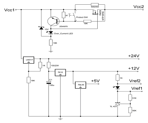
The current protect limit determined by Rds of PMOS / 2SA970 / 18K / R*
I also adjust R* and make current protect limit >=2.5A, but when temperature increase, The Rds increase,so the current protect limit reduce.
When CT3 not being measuring, only LM317 heat, Q1~Q4 not heat.
You only need a thickness is 4mm, the side length of 40mmx40mm, the length is 12cm of angle aluminum as a heat sink is enough.
Because measure process is fast, If a curve have 100 point, It only need less 3 second then OK, and the current is from low to high,Q1~Q4 work in high-power is less 1 second. So Q1~Q4 is a little warm.
But if you set AD sample to more than 18 times, and set voltage step amplitude is too small, The measure process will long time,Q1~Q4 heat will increase.
The CT3 protect circuit is below
The current protect limit determined by Rds of PMOS / 2SA970 / 18K / R*
I also adjust R* and make current protect limit >=2.5A, but when temperature increase, The Rds increase,so the current protect limit reduce.
When CT3 not being measuring, only LM317 heat, Q1~Q4 not heat.
You only need a thickness is 4mm, the side length of 40mmx40mm, the length is 12cm of angle aluminum as a heat sink is enough.
Because measure process is fast, If a curve have 100 point, It only need less 3 second then OK, and the current is from low to high,Q1~Q4 work in high-power is less 1 second. So Q1~Q4 is a little warm.
But if you set AD sample to more than 18 times, and set voltage step amplitude is too small, The measure process will long time,Q1~Q4 heat will increase.
Hi locky
Tanks for your explanation about current limit
I have one tought about this
Why would one want to test at such hi currents if then when in use the devices are limited by the amount of heath they dissipate
For example (on my F5 TO247) will never be biased so to dissipate more than 50W.
with 25 V rails that would be 2 A.
Can I ask you If you could explain how to set up the formulas for testing VGS of P channels Mosfets
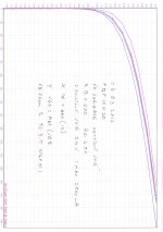
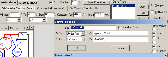
You can press 'Load condition' and choice 'PMOS Vgs-Id(Fix Vce)' when you want to test PMOS.
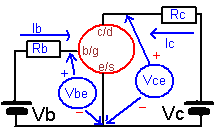
Combined with the following schematic
Because PMOS need negative Vgs,so set Vb is from 0 to -6V,step 0.1V
Constant Vce is -10V mean Vds is -10V.
Because PMOS gate current is tiny,so RB you can choice 6K or 500ohm or 91K
If you select RC=75ohm, The max current is about 400mA
If you select RC=4.5ohm, the max current more 2.5A
The Curve type Define window:
X-Axis define is Vgs=abs(Vbe) ,Y-Axis define is Id=abs(Ic)
Function abs() mean absolute value,
Becasue PMOS Vgs and Id is negative,so their Vgs-Id curve will be in the third quadrant, Use abs() function to change them to first quadrant.
Attachments

- Status
- This old topic is closed. If you want to reopen this topic, contact a moderator using the "Report Post" button.
- Home
- Amplifiers
- Solid State
- DIY Curve Tracer for PC