Lumba Ogir,
Thanks for the further part sugestions, I'm fairly new to using JFETs in power amps, so it's really useful. I might sound against the idea of using FETs but it's down partly to inexperience with them and partly to playing the devils advocate") I'm always willing to experiment and adjust my opinions...
I'm always willing to experiment and adjust my opinions...
I think the idea that the CFP is inherantly unstable comes from people (doing what I intially did) forgetting to degenerate the compound pair back down to the same gm as a single transistor. Adding such a large amount of extra Aol unchecked will make most amplifiers very hard to tame. Done properly, the CFP is a super-beta transistor with lots of local NFB by degeneration, which makes the V/I plot extremely linear, and yet it still has enough gm left to provide good open-loop gain for the whole amp for global NFB; it seems ideal to me. The cascode does increase stage gain (a good thing if the IP pair degeneration is excessive), but this again is a case of increasing local NFB and adjusting compensation to make sure the resulting amplifier is stable.
I think the comparison between BJT and JFET is more fair if you specify using a cascode, though I think you then need to compare good JFETs against good low voltage BJTs with cascode. For example I have a box of MAT02 (AZ , from the middle of the wafer) supermatched pairs; I'd be amazed to see this level of performance from N-JFETs, at least in the 'tens to hundreds of ohm' souce impedance range we normally see with power amp LTP inputs.
I'd be interested to see an amp with a JFET input stage you commend, so I can do some analysis on it and better understand where you're comming from?
Cheers,
Thanks for the further part sugestions, I'm fairly new to using JFETs in power amps, so it's really useful. I might sound against the idea of using FETs but it's down partly to inexperience with them and partly to playing the devils advocate
I'm always willing to experiment and adjust my opinions...I think the idea that the CFP is inherantly unstable comes from people (doing what I intially did) forgetting to degenerate the compound pair back down to the same gm as a single transistor. Adding such a large amount of extra Aol unchecked will make most amplifiers very hard to tame. Done properly, the CFP is a super-beta transistor with lots of local NFB by degeneration, which makes the V/I plot extremely linear, and yet it still has enough gm left to provide good open-loop gain for the whole amp for global NFB; it seems ideal to me. The cascode does increase stage gain (a good thing if the IP pair degeneration is excessive), but this again is a case of increasing local NFB and adjusting compensation to make sure the resulting amplifier is stable.
I think the comparison between BJT and JFET is more fair if you specify using a cascode, though I think you then need to compare good JFETs against good low voltage BJTs with cascode. For example I have a box of MAT02 (AZ , from the middle of the wafer) supermatched pairs; I'd be amazed to see this level of performance from N-JFETs, at least in the 'tens to hundreds of ohm' souce impedance range we normally see with power amp LTP inputs.
I'd be interested to see an amp with a JFET input stage you commend, so I can do some analysis on it and better understand where you're comming from?
Cheers,
Try Jfet/Bjt cfp, works ok. To obtain higher gm with jfets just parralel two or more of them.
Hi,
I've used this (jfet, then bjt in CFP) in a commercial design that needed very high imput impedance - it does indeed work great in that situation.
In that design the impedance into the FET gate was fixed and quite high (several k) from a transformer; the transformer was terminated precicely and the input stage could not add any additional load; I think this is a bit different from the situation with a power amp, where generally the lower the input impedance the better (might be <1 ohm at the input connector).
Paralelling jfets is interesting, since they're essentialy transconductance devices so you should double gm when you double the number of transistors....
Cheers,
Atomicplayboy,
the JFET-BJT combination gives better stability mainly due to the much wider bandwidth of JFETs. I don`t anticipate any trouble.
The benefit of supermatched pairs is limited. Sonic performance is of primary importance and the available discrete transistors are better in that regard.
While considering stability (and noise), the input parallel resistor value for a transconductance stage should be set high to allow amplification of weak signals, or in case of high output-impedance signal sources, to obtain large current gain. 47kOhm could be a good compromise here.
Paralleling JFETs (or BJTs) is not very interesting. JFETs have large current gain and small voltage gain, the latter we want to keep at a minimum, anyway. Their task is to convert voltage to current and they do that pretty accurately (unlike BJTs).
homemodder,
you don`t read my posts, do you?
(J)FETs do not have appropriate properties for voltage amplification.
Crss for 2SJ74 is 32pF @ 10Vds, a way too high price for the (unnecessary) large Gm. It`s not just about multiplied capacitances, but a muddled signal processing. Noise is not that big issue here. By the way, power supply ripple and the signal related dynamic noise caused by global feedback is much worse.
Hi Lumba, you've got me on the hook with this one
Also, IIRC the voltage-current transfer function of a JFET is square-law. The same for a BJT is tanh. Both are non-linear (though I'll concede the FET is better), but because the BJT has so much more gm to start with, we can do a lot more to linearise it's transfer function.
I'm enjoying this discussion; please continue
Cheers,
I'm not sure where you're coming from here. JFETs have higher parasitic capacitance than BJTs and they're usually operated with higher impedances, so should be slower than BJTs? Also, with BJTs it's surely just a matter of device slection; make sure the Ft of the first transistor is an octave or two more than the second transistor (yes I need to look at this in my amp circuit; thanks for reminding me) and it should be fine.the JFET-BJT combination gives better stability mainly due to the much wider bandwidth of JFETs.
I disagree on this one. One of the reasons to use a long-tail pair is cancellation of even-order harmonics; this is down to transistor matching and correct current balancing. JFETs are very poor in this regard (although the extra even-order harmonics might be flattering to the signal). Also good supermatch pairs have equal performance to good single transistors, with the advantage that they track perfectly with temperature. You just have to pay for the good ones...The benefit of supermatched pairs is limited. Sonic performance is of primary importance and the available discrete transistors are better in that regard.
Isn't paralleling up regular JFETs how they fab the 'high gm' parts that are suppose to compete with single BJTs?Paralleling JFETs (or BJTs) is not very interesting. JFETs have large current gain and small voltage gain, the latter we want to keep at a minimum, anyway. Their task is to convert voltage to current and they do that pretty accurately (unlike BJTs).
Also, IIRC the voltage-current transfer function of a JFET is square-law. The same for a BJT is tanh. Both are non-linear (though I'll concede the FET is better), but because the BJT has so much more gm to start with, we can do a lot more to linearise it's transfer function.
I'm enjoying this discussion; please continue
Cheers,
Hi Lumba,
I agree that we have quite different ideas about how to do an input stage, but that's part of the fun You don't normally gain anything by discussing with people you completely agree with...
Anyway I've etched 4 boards tonight and will drill and populate one tomorrow. I'm planning to tweak/debug at the weekend, then do full testing on an AP next week. Assuming they work and I haven't done something stupid, I'll post the schem/artwork then.
Cheers,
I agree that we have quite different ideas about how to do an input stage, but that's part of the fun
You don't normally gain anything by discussing with people you completely agree with...Anyway I've etched 4 boards tonight and will drill and populate one tomorrow. I'm planning to tweak/debug at the weekend, then do full testing on an AP next week. Assuming they work and I haven't done something stupid, I'll post the schem/artwork then.
Cheers,
Ok chaps,
First PCB built up and tested - everything I can test at home looks good, time to get it on an AP at work next week
A few mechanical issues (and component rationalisiations) came up, so I'll be doing another PCB revision this week, but then I think it is good to go.
Thanks for all the comments and advice, you helped me avoid a few clangers
Cheers,
Attachments
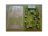

Thanks, I'm quite pleased with how it came out
I like screw/stud connections for anything I might have to remove for service, and of course they do look good too!
I can't wait to see how this thing measures up, though putting a new design to the acid test is always a bit nerve wracking after all the work that went into it...
Cheers,
I like screw/stud connections for anything I might have to remove for service, and of course they do look good too!
I can't wait to see how this thing measures up, though putting a new design to the acid test is always a bit nerve wracking after all the work that went into it...
Cheers,
- Status
- This old topic is closed. If you want to reopen this topic, contact a moderator using the "Report Post" button.
- Home
- Amplifiers
- Solid State
- Can I have some comments on this design?