I own a C-Audio SR 707
The voltage rails are 200vdc rail to rail (+100 / -100)
The output devices in the original mk 1 version were Hitachi 2sk135 / 2sj50 pairs. 160V drain to source
The output devices in the later versions were the Magnatec BUZ900 / BUZ905 pairs. Again 160V drain to source
There are 32 mosfets in total.
My Amp is the later version with the Magnatec devices.
Of the original 32 mosfets over 50% have failed!
Over many months I have been accumulating Hitachi 2sk135 / 2sj50 Fets
And now have enough to consider rebuilding the amp.
The transformer is multi tapped and I have the option to reduce the rail voltages.
Alternatives are
+100 / -100 for SR707 rated at 1175W / 2 Ohm, 825W / 4 Ohm, & 488 / 8 Ohm
+90 / -90 for SR606 rated at 750W/ 2 Ohm, 625W / 4 Ohm, & 390W / 8 Ohm
+75 /- 75 for SR404 rated at 500W /2 Ohm, 466W / 4 Ohm, & 283W / 8 Ohm
I am considering using the 606 option 180V rail to rail.
I assume that the maximum Drain to Source voltage would be 1 voltage rail plus the maximum output swing voltage of the amplifier.
Looking at the 8 ohm performance of the 606 Maximum output voltage would be 56VRMS so 79 V peak.
Adding that to the 90v rail gives a max drain to source voltage of 169V.
Obviously reducing the rail to rail voltage by 20V will reduce the chance of failure of the amplifier.
Questions.
Are my assumptions about how to calculate the drain to source voltage correct?
Will reducing the voltage by 20 V be enough to ensure the mosfets survive?
Attachments
Nelson
By that I assume that you are telling me I am going to overstress the output devices by using 180V rail to rail.
I do have the option of aquiring 32 off 2sj56 2sk176 200V devices.
This would cost me about £250 British pounds.
I already have 32 off of the 160V part. But could utilise them elswhere.
My Assumptions probably arise from the fact that in its standard form this amp is so over voltage and me trying to justify that!
Regards.
I already have 32 off of the 160V part. But could utilise them elswhere.
I would tap the transformer down to the +/-75 figure and
use the parts you have.
I would tap the transformer down to the +/-75 figure and
use the parts you have.
OK. I will try the amp at 150v rails. Not much to loose by trying!
I Have a complete schematic, and there are ony really a couple of resistors that are changed. These seem to effect the gain (feedback) and the clip indication circuit.
Have a look at the Exicon branded 200V devices from Profusion.
The problem I have with the Exicon (Semelab) parts is I have been warned by 2 separate well respected designers, that these components are not really reliable when pushed to the limits. Unlike the Hitachi parts.
The Sr 404 used 24 output devices, but I will try fitting all 32 in place.
Hopefully this will allow me to run the amp as a 4 Ohm loaded mono bridge to get some useful power. Drivers are 2, off Fane XB 600w RMS 8Ohm These will take 900 to 1200w with some care.
Crossover is a tweeked Behringer DCX 2496 so the signal is well managed!
The other mod I will try is to change the gate resistors increasing the resistance from 560R to 680R for the P channel and 1k0 for the N channel to compensate for the lower capacitance.
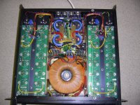
The original amplifier had ceramic caps on some of the N channel devices but not all of them. You can see them in the photo in my first post.
I would also like to add some extra local decoupling adjacent to the mosfets, but will need to work out how to add a ground rail as there is no 0V track on the driver PCB.
Thanks for the input.
Hi,
does the amp have a current limiting circuit?
This can cause extreme over-voltage back EMF into the output devices causing premature failure.
The standard protection for this form of abuse is to fit medium current diodes between the supplies rails and the output rail.
It is also worthwhile checking to see if diodes are fitted between the supply rails and power ground. Those 4 diodes/channel (1n4004) will cost cents/pennies.
32devices in one amplifier.
How are these arranged?
8pair per channel?
or
is each channel bridged leaving just 4pair per half bridge?
The amp options seem to show that the amp is capable of driving a 2r0 load. I see they use 2ohm in the power spec but we know they mean 2r0.
I do not see any duty cycle spec for this low resistance load.
I do not see any confirmation that the amp is capable of driving a 2ohm load (a real speaker). On the evidence of the 8r0, 4r0 and 2r0 power outputs I would NOT consider this amp in any of it's voltage forms as capable of driving 2ohms properly.
Last edited:
I can not see any reference to, or any circuitry, that could be current limiting.
There are 2 In4004 between the voltage rails and the output rail, per channel. These are visible in the photo in my first post. Have not spotted any diodes on the supply rails to ground.
Amplifier topology is Class A/B - Balanced op amp input. Then first 2 stages (differential pair and VAS) are like the hitachi mosfet application notes, but with added constant current sources.
The driver section is more complicated, A pair of transistors, between each supply rail and the bias setting circuitry, are AC coupled to the feedback / output rail. Then a zener voltage limit, and finally a pair of driver transistors.
The spec talks of active headroom circuitry, that raises the driver voltage above the output stage.
The 2R0 loading is average continuous rating in the spec sheet.
The output devices are arranged in 8 pairs per channel.
This certainly isn't a toy amplifier. The weight is 29kg. The last list price I can remember was £1450 (last century money).
All I know is that when it worked, it drove my pair of Fane XB drivers in bridge mode, thats nearly 1200w per driver which is their peak rating.
Obviously this is pushing the SR707 too hard, as it broke!
The speakers are still fine!
Reasoning behind still using the amp in bridge mode is to try to extract some useful power from the amp, Otherwise I will need to invest in a new bass amp, and just use this one for the mids.
The lower voltage SR404 had less Mosfets, 24 in total. I going to fit all 32 and use the fets at a safe voltage, not 40V above their rating.
If it only makes the rated 1000w / 4R0 loading in bridge mode this is only 62 watts per mosfet pair. I have a feeling it should be capable of more than this.
Not sure of the VA rating of the transformer, but it has a soft start and a 15A internal AC fuse!
my humble opinion .....
to evaluate a complete device as is or as was the amplifier circuit/rail voltage /related outputs is only 25% of the story the rest 75% is the protection devices existing inside the amp, how well work , exactly where and how take effect .and how much of your sound quality remove .
example : a crappy construction i ve made using brother of quasi circuit way too small trafo ( existing allready ) way too small transitors like tip 3055 abused like hell always playing at clip never failed .... do you know why ????
cause the trafo is too small and rails dive like hell ..... of course the sound that comes from is probably teriible .... but up too 100+100 watts plays relativelly well .
now if you work with Andrew T calculations a numark factory made amplifier that i have with very big trafo ,quite high rail voltage, and only 6 outs per ch will not stand a chance in PA use ..... well actually it does .... do you know why ???
cause it features a quite sophisticated VI limiter , a soft cliping circuit, and an input limmiter circuit ,
Pa amplifiers comercially made is a diferent ballgame and schematic, topology ,number of outs and rails is only 25% of the story .
you can overdesign as much as you like in a PA amplifier but this is not the solution to protect it against abuse .....
humble regards
I think bridging without the knowledge is your problem................................The 2R0 loading is average continuous rating in the spec sheet.....................
.................................All I know is that when it worked, it drove my pair of Fane XB drivers in bridge mode, thats nearly 1200w per driver which is their peak rating.
Obviously this is pushing the SR707 too hard, as it broke!
Nearly 1200W+1200W into what load?
825W into 4r0 from the spec sheet indicates that a bridged pair will give 1650W into 8r0.
To get 2400W in bridged mode, the load would need to be less than 8r0.
I guess the amp could deliver, in the short term, 2400W bridged into 6r0.
That is equivalent to 1200W into 3r0.
Your lack of know how and understanding broke the amplifier.
I can tell and previously told you that this amp is probably not rated for speakers of less than 4ohms. You asked it to drive approximately 3ohms or maybe worse.
The speakers didn't break the amplifier. The installer/operator broke the amplifier.
I always ran the amplifier driver by a compessor limiter in order to manage the levels and avoid clipping. Compression was kept low ratio and limiting would cause gain reduction to the signal.
The practice of running 2 x 8 Ohm Speakers in parallel to make a 4 Ohm Load bridged across an amplifer is not uncommon in PA usage.
Of course it would of been better if I had used 4 Ohm Speakers and run the amp in stereo. But what do you do when 4000 people turn up, and want to party!
This still leaves the issue of the high voltage rails.
I really have been (privately) warned off using the Semelab mosfets in this amplifier, by two separate respected amplifier designers. Of course that was exactly what this amplifier was originally built with.
The Mk 1 version with Hitachi output stages are often still working, and regularly found on ebay.
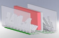
I did actually develop an idea to rebuild the amplifer with T03 plastic output devices, but did not go ahead with it at the time due to cost and Family issues. (Life is so much more important than any of this!) I did however make a set of the aluminium top heatsinks as the attached jpeg.
The practice of running 2 x 8 Ohm Speakers in parallel to make a 4 Ohm Load bridged across an amplifer is not uncommon in PA usage.
Of course it would of been better if I had used 4 Ohm Speakers and run the amp in stereo. But what do you do when 4000 people turn up, and want to party!
This still leaves the issue of the high voltage rails.
I really have been (privately) warned off using the Semelab mosfets in this amplifier, by two separate respected amplifier designers. Of course that was exactly what this amplifier was originally built with.
The Mk 1 version with Hitachi output stages are often still working, and regularly found on ebay.
I did actually develop an idea to rebuild the amplifer with T03 plastic output devices, but did not go ahead with it at the time due to cost and Family issues. (Life is so much more important than any of this!) I did however make a set of the aluminium top heatsinks as the attached jpeg.
Attachments
- Status
- This old topic is closed. If you want to reopen this topic, contact a moderator using the "Report Post" button.
- Home
- Amplifiers
- Solid State
- Maximum Voltage for Mosfet Output Stage?