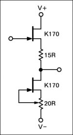
I suggested to someone that they connect the offset trim pot in this classic JFET buffer as shown in the schematic below, the reason being that it keeps the current source's current from flowing through the trimpot's wiper.
I was told "It won't work."
Now, my memory isn't what it used to be, but I'm pretty damn sure I'd used this connection method before and it worked just fine. Nor can I think of any reason why it wouldn't work.
I don't have any JFETs on hand at the moment or I'd just stuff up a breadboard and check for myself. So I thought I'd put it before y'all.
Is my memory failing me or will this method indeed work?
Thanks.
se
Attachments
Thanks, Gary.
Yes, I'm already familiar with that basic classic JFET buffer.
The issue at hand concerned how the trimpot was used. In other words, how I have it drawn in the schematic where the wiper goes directly to the JFET's gate versus having both the gate and the trimpot's wiper going to the negative rail as is also commonly done.
The way I see it, both will work just fine, but as I drew it, it has the advantage of not having any current flowing through the trimpot's wiper.
se
Tek always had protection on the input J-FET gate. This usually consisted of a low leakage, low capacitance diode connected between the gate and the negative supply, cathode to gate, anode to the negative supply. On the vertical inputs it was common to have an RC combo consisting 470K resistor and .001uf capacitor between the input and gate of the upper J-JET. The resistor provided current limiting in the event of overdrive. In the positive overdrive condition the J-FET forward biases. In the negative direction the protection diode forward biases limiting the voltage on the J-FET gate.
To see the many variations of this circuit look in old Tek scope manuals. Look at the vertical input buffer or the external trigger input. To down load old Tek manuals go to bama.sbc.edu/. There is an amazing amount of information to be found perusing through the old manuals, both solid state and tubes (provided that the scans have the schematics included as it seems that some don't).
Gary
SY said:That's absolutely the way to do it. Only thing I'd add is a safety resistor between gate and negative in case the wiper poops out.
Aye. Good idea. Thanks!
And thanks, Gary for the additional info and the link to the BAMA site!
se
Gary P said:Tek always had protection on the input J-FET gate. This usually consisted of a low leakage, low capacitance diode connected between the gate and the negative supply, cathode to gate, anode to the negative supply. On the vertical inputs it was common to have an RC combo consisting 470K resistor and .001uf capacitor between the input and gate of the upper J-JET. The resistor provided current limiting in the event of overdrive. In the positive overdrive condition the J-FET forward biases. In the negative direction the protection diode forward biases limiting the voltage on the J-FET gate.
To see the many variations of this circuit look in old Tek scope manuals. Look at the vertical input buffer or the external trigger input. To down load old Tek manuals go to bama.sbc.edu/. There is an amazing amount of information to be found perusing through the old manuals, both solid state and tubes (provided that the scans have the schematics included as it seems that some don't).
I would say, Tektronix is among few American companies that had excellent designers. I can name 2 more: Collins Radio and Altec Lansing.
Hi Anatoliy,
I dare say there are many others out there, too many to list. I'm talking about design excellence here. Hughes Aerospace and Itty-Bitty (IBM) are also examples of fine design work left out of the list.
Hi Steve,
-Chris
You can't leave out Agilent/HP from your list! I dare say that stuff is every bit as good as your other mentions. Tektronix - absolutely!I would say, Tektronix is among few American companies that had excellent designers. I can name 2 more: Collins Radio and Altec Lansing.
I dare say there are many others out there, too many to list. I'm talking about design excellence here. Hughes Aerospace and Itty-Bitty (IBM) are also examples of fine design work left out of the list.
Hi Steve,
Did you get any reasons, or just a flat statement? That circuit is indeed a classic and does work, even as drawn without the finer points of "just-in-case" protection. Of course, bleeding edge audio work can not include anything that may affect the sound at all.I was told "It won't work."
-Chris
Lumba Ogir said:Hi,
what are the JFETs supposed to be proactively protected against by low capacitance diodes, trimpots, capacitors and reverse biasing? Swine flu? They have an outstanding ability to protect themselves when just being biased suitably and cleanly.
Voltages that might cause the gate to channel oxide barrier to fail, and ESD discharges. The citation was for test equipment inputs.
The pot is used to set the operating current, and by inference probably to set the q point of the output to 0V. And yes it works just fine, and as SY indicated a resistor from wiper to negative supply will prevent fet frying mischief if the wiper goes bad.
Incidentally the wide variation in transconductance from fet to fet makes this circuit a reasonable idea if fets cannot be selected.
anatech said:Did you get any reasons, or just a flat statement? That circuit is indeed a classic and does work, even as drawn without the finer points of "just-in-case" protection. Of course, bleeding edge audio work can not include anything that may affect the sound at all.
I was given reasons of sorts.
I'll see if I can talk the person who said it wouldn't work into giving his reasons in his own words.
se
Hi keantoken,
I think that this may be one of those cases where you may be further ahead to build, then measure. The circuit is dead simple and it should be easy to make room for a possible extra component or two. I'd tend to build it on perf. board first anyway. Easy to modify the circuit to improve performance in case it is found lacking.
-Chris")
I think that this may be one of those cases where you may be further ahead to build, then measure. The circuit is dead simple and it should be easy to make room for a possible extra component or two. I'd tend to build it on perf. board first anyway. Easy to modify the circuit to improve performance in case it is found lacking.
-Chris
kevinkr,
It can be mentioned that the gate-channel junction does not exhibit the typical P-N junction diode reverse breakdown voltage characteristic. The gate reverse current (Igss) breakpoint depends mainly on Ids and Vgd (not Vds).
Electrostatic discharge implies a momentary current. The gate to channel P-N juntion is not built to handle any substantial current. JFETs should never be forward biased.Voltages that might cause the gate to channel oxide barrier to fail, and ESD discharges.
It can be mentioned that the gate-channel junction does not exhibit the typical P-N junction diode reverse breakdown voltage characteristic. The gate reverse current (Igss) breakpoint depends mainly on Ids and Vgd (not Vds).
Lumba Ogir said:kevinkr,
Electrostatic discharge implies a momentary current. The gate to channel P-N juntion is not built to handle any substantial current. JFETs should never be forward biased.
It can be mentioned that the gate-channel junction does not exhibit the typical P-N junction diode reverse breakdown voltage characteristic. The gate reverse current (Igss) breakpoint depends mainly on Ids and Vgd (not Vds).
It does not matter: somebody said you so, or you googled for it; anyway it is irrelevant. I is a good practice to protect inputs from damage. Even foolproof them.
Lumba Ogir said:kevinkr,
Electrostatic discharge implies a momentary current. The gate to channel P-N juntion is not built to handle any substantial current. JFETs should never be forward biased.
It can be mentioned that the gate-channel junction does not exhibit the typical P-N junction diode reverse breakdown voltage characteristic. The gate reverse current (Igss) breakpoint depends mainly on Ids and Vgd (not Vds).
Having worked in the semi-conductor test industry it doesn't matter whether the ESD is a momentary current or not, it just melts everything in the vicinity of the point where it punched through the gate. (It is quite a lot of fun looking through an electron microscope at the resulting damage.) Otherwise what you say is quite true for jfets. My experience designing outboard processor electronics in the MI industry gave me some graphic examples of the same thing. Best case you now have a parametrically degraded jfet (and yes mosfets are a different animal and a lot more susceptible) or a dead jfet. I have seen both usually during our local cold, dry winter. It does not hurt to protect them if your commercial reputation is on the line. (And diodes aren't always necessary.)
- Status
- This old topic is closed. If you want to reopen this topic, contact a moderator using the "Report Post" button.
- Home
- Amplifiers
- Solid State
- "It won't work"